Basic Rockets · Volume 1
How a Model Rocket Works
The parts of a kit rocket and what each one does; how a black-powder motor makes thrust, then smoke, then a puff that blows the nose off; how to read a motor code; why the center of gravity has to lead the center of pressure; and the six stages of a flight from button to recovery
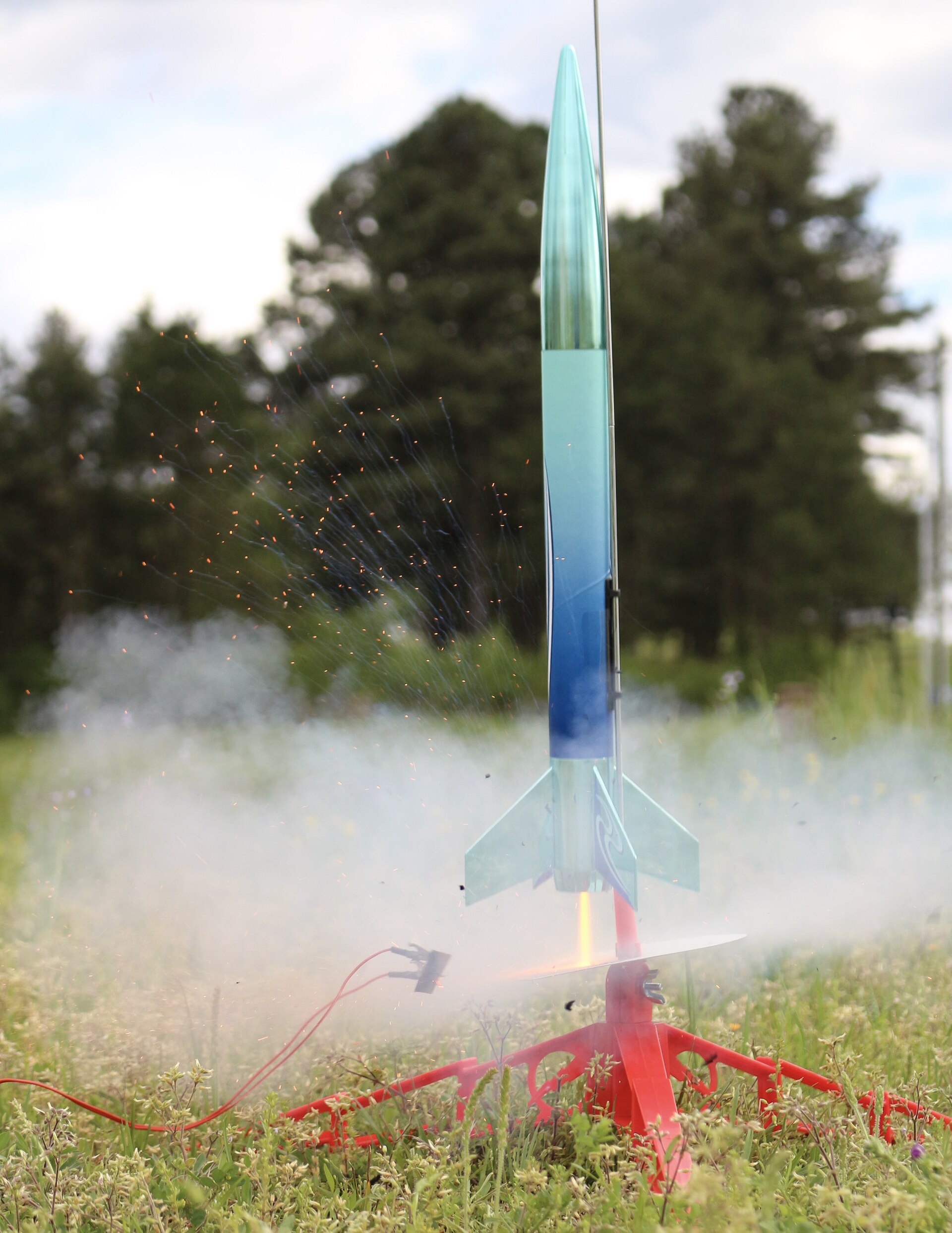
Introduction
I have been building model rockets since I was about seven years old. Over the years I built nearly every rocket in the Estes catalog, and every birthday brought more kits. Once the kits ran out, I started designing my own and building them from scratch. My favorites are still the classics: the Mars Snooper (I have built it from the Estes kit and again as a much larger high-power rocket), the Mars Lander, the Andromeda, the Saturn V and the Mega Der Red Max, the big brother of the classic Der Red Max. I fly high power too, as a member of both the NAR and Tripoli. My first launch controller was one I designed and built myself at about eleven. My early rockets carried film cameras. Later ones carried electronic video, electronic parachute deployment, GPS location and altitude reporting.
All of that starts in the same place: a cardboard tube, a balsa fin, a paper-cased motor and a parachute. This volume covers how those parts work together. It does not cover how to build them (that is the next volume). Everything later in this site depends on the ideas here: the motor code, the balance between center of gravity and center of pressure, and the six stages of a flight. That includes high-power airframes, reloadable motors, electronic deployment and RockSim designs.
1.1 What counts as a model rocket
“Model rocket” is a defined term with three overlapping definitions: a hobby one, a safety-code one and a legal one.
The hobby definition. A model rocket is a light, reusable flying model made of paper, wood or breakable plastic. It is lifted by a commercially made, pre-loaded motor and returned to the ground by a recovery device so that it can fly again. The flyer never mixes or handles propellant. The motor arrives sealed and certified, and the flyer only fits it into the rocket and fits an igniter into its nozzle. This separation dates from the hobby’s founding in the late 1950s, and it is what made rocketry safe enough to sell in hobby shops. The early history, from Orville Carlisle’s first modern model rocket and motor in 1954 to G. Harry Stine and Model Missiles Inc. in 1957 and Vern Estes’s motor-making machine, belongs to the History dive.
The safety-code definition. The National Association of Rocketry (NAR) Model Rocket Safety Code limits a model rocket to 1,500 grams (53 oz) at liftoff, 125 grams (4.4 oz) of propellant, and 320 newton-seconds of total installed impulse. The impulse limit is the equivalent of two G motors. Above those limits the rocket is a high-power rocket. High-power rockets have their own safety code, certification and motors, all covered in the High-Power Rockets and Motors dives. The NAR code is also the basis of the U.S. fire-code standard for model rocketry, NFPA 1122.
The legal definition. The U.S. Federal Aviation Administration places model rockets in Class 1 of its amateur-rocket rules (14 CFR 101.22). A Class 1 rocket:
- uses no more than 125 g of slow-burning propellant,
- is made of paper, wood or breakable plastic,
- contains no substantial metal parts, and
- weighs no more than 1,500 g including propellant.
A Class 1 rocket flown within the rules’ operating limits needs no FAA notification. Those limits include staying clear of clouds, aircraft and people. The 1,500 g and 125 g figures date from a 1994 FAA rule, which raised the earlier 16 oz and 4 oz limits after petitions from the NAR and the Hobby Industry Association. Older books and kit instructions sometimes still quote the lower numbers.
The three definitions describe the same rocket: light, frangible, store-bought motor, recoverable. A typical Estes kit sits far inside all of them. A beginner’s rocket on a C motor weighs perhaps 30–60 g and carries about 12 g of propellant.
1.2 The parts of a model rocket
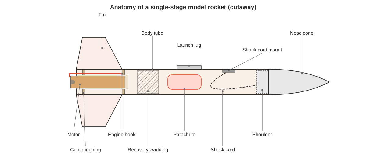
Nearly every single-stage kit, from a 1960s Alpha to a current Estes model, uses the same dozen parts. Figure 1 shows them in a cutaway.
1.2.1 Nose cone
The nose cone is the forward end of the rocket. It cuts the air and, on most rockets, it is the plug that the ejection charge blows out to release the parachute. The shoulder is the narrower part that slides into the body tube. It must fit snugly enough to stay put under thrust and loosely enough to come out cleanly at ejection. Getting that fit right is a large part of getting good recovery.
Kit nose cones are either turned balsa (common in older kits and many current ones) or blow-moulded or injection-moulded plastic (most current Estes kits). Plastic cones are hollow and light. Many plastic cones have a moulded eyelet or loop for the shock cord, and some have a hollow shoulder that can take clay ballast. Balsa cones get a screw eye.
The shape matters less at model-rocket speeds than it does on a high-power rocket going transonic. Still, the classic profiles all appear in kits:
- Ogive — the curved “bullet” of most sport rockets.
- Conical — the simple point of many scale and contest models.
- Elliptical — a blunt, rounded nose that does well at low subsonic speed.
- Parabolic — between ogive and elliptical.
Nose-cone drag at hobby speeds is dominated by surface finish, so a smooth parabolic or ogive nose has a real advantage over a rough one of any shape.
1.2.2 Body tube
The body tube is the spine of the rocket. Hobby body tubes are spiral-wound kraft paper: several plies wound on a mandrel, glued and cut to length. Better tubes have a glassine outer ply that takes paint well. The seams show as a faint spiral, which needs filling before a good paint job (the Jigs and Finishing dive covers how).
Estes catalogues its tubes with BT (“body tube”) numbers. The numbers are not dimensions. BT-5 is called that because it is smaller than BT-10, and BT-55 because it falls between BT-50 and BT-60. Most kits use the six sizes below:
Table 1 — Estes catalogues its tubes with BT ("body tube") numbers. The numbers are not dimensions. BT-5 is called that because it is smaller than BT-10, and BT-55 because it falls between BT-50 and BT-60. Most kits use the six sizes below
| Tube | Inside diameter | Outside diameter | Typical use |
|---|---|---|---|
| BT-5 | 0.515 in (13.1 mm) | 0.541 in (13.7 mm) | Mini-motor rockets; 13 mm motor-mount tube |
| BT-20 | 0.710 in (18.0 mm) | 0.736 in (18.7 mm) | The classic slim sport rocket (Alpha-class) and the standard 18 mm motor mount |
| BT-50 | 0.950 in (24.1 mm) | 0.976 in (24.8 mm) | Mid-size sport rockets; the 24 mm motor mount |
| BT-55 | 1.283 in (32.6 mm) | 1.325 in (33.7 mm) | Larger sport rockets and payload sections |
| BT-60 | 1.595 in (40.5 mm) | 1.637 in (41.6 mm) | Big sport models and scale stages |
| BT-80 | 2.558 in (65.0 mm) | 2.600 in (66.0 mm) | The “big” Estes size: large sport and scale models |
The diameters are as compiled in the community OpenRocket component database and an Australian club’s tube table. Estes does not publish an official dimension sheet, and tubes from other makers (Semroc, Totally Tubular, Apogee, BMS) that use the same names can differ by a few thousandths of an inch.
The motor-mount sizes are designed to fit each other: an 18 mm motor fits BT-20, and a 24 mm motor fits BT-50. A BT-20 mount centered inside a BT-55 or BT-60 body is the most common layout in the hobby.
1.2.3 Fins
Fins give a rocket its stability (see Stability), and they take most of the punishment when it lands. Kit fins are usually balsa sheet, 1/16 to 1/8 in (1.6–3.2 mm) thick. Larger or tougher rockets use basswood, aircraft plywood or plastic (moulded fin cans, or fins cut from styrene sheet).
On balsa, the grain direction is the one detail that decides whether a fin survives. The grain should run roughly parallel to the fin’s leading edge so the long fibres carry the load. A fin cut with the grain across its span will snap off at the first hard landing. Fins are glued straight onto the tube with a reinforcing fillet of glue along the root, or on sturdier rockets set through the wall of the tube onto the motor mount. Fin shape, airfoiling and alignment jigs are covered in the next volume and in the Jigs and Finishing dive.
1.2.4 Launch lug
The launch lug is a short paper or plastic straw glued to the side of the body. It slides over the launch rod and guides the rocket for the first metre or so of flight, until it is moving fast enough for the fins to steer it. Lug size matches rod size: 1/8 in (3.2 mm) rods for small rockets and 3/16 in (4.8 mm) for heavier ones, with 1/4 in (6.4 mm) and launch rails used for larger rockets. A lug that is too loose lets the rocket wobble on the rod. One glued crooked makes it bind.
1.2.5 Motor mount
The motor mount holds the motor in line with the rocket’s axis and passes the thrust into the airframe. In a kit it is a short tube of the motor’s diameter with:
- a thrust ring (or motor block) glued inside its forward end, which the motor pushes against;
- centering rings, cardboard or plywood discs that hold the mount tube concentric inside a larger body tube; and
- an engine hook, a spring-steel clip that snaps over the aft end of the motor. It stops the ejection charge from pushing the motor out of the back of the rocket instead of the nose out of the front.
On a rocket whose body tube is the motor’s own diameter (BT-20 on an 18 mm motor), the body tube is the motor mount. Only a thrust ring and a hook are needed. Motor retention matters more as rockets get heavier. The High-Power Rockets dive covers screw-on retainers and the reasons a friction fit stops being enough.
1.2.6 Recovery system
The recovery system is everything forward of the motor that brings the rocket back:
- Recovery wadding, a flame-resistant tissue packed above the motor. The ejection charge is a hot, fast puff of burning black powder. Without wadding it would melt or scorch a plastic parachute. Some rockets use a reusable baffle or a Nomex blanket instead.
- Shock cord, an elastic or Kevlar-and-elastic cord that joins the body to the nose cone. It absorbs the snatch when the nose pops off at speed.
- Shock-cord mount. In the classic Estes kit this is a folded-paper mount glued inside the forward end of the body tube. Stronger rockets tie the cord to the motor mount with a Kevlar leader.
- The recovery device itself: a parachute or a streamer on a sport rocket, or a glider wing, helicopter blades or deliberate tumbling on more unusual designs. An overview of how each works appears below. Sizing, packing and electronic deployment are covered in the Recovery dive.
1.3 Motors in brief
A full treatment of motors, covering how they are made, the propellant chemistry, thrust curves, choosing the right one and buying them, has its own dive. The Motors dive’s first volume covers model-rocket motors: black powder and single-use composite. Its second covers high-power reloadable and buildable motors. What follows is the minimum needed to understand a kit rocket.
1.3.1 How a black-powder motor works
The classic Estes motor is a heavy paper tube packed with four pressed layers. Figure 2 shows them. From the back of the rocket forward:
- A clay nozzle, a pressed ceramic plug with a hole through it. The hole narrows to a throat and then flares out, which speeds up the exhaust and turns pressure into thrust.
- The propellant grain, compressed black powder. On most Estes motors the grain is end-burning: it burns from the nozzle end forward like a cigarette, with a small conical cavity at the nozzle to give the igniter more surface to light. Some larger black-powder motors are cored for a higher initial thrust.
- The delay element, a slow-burning composition that produces no useful thrust but trails smoke. It lets the rocket coast upward after burnout, and the smoke trail helps spectators follow the rocket.
- The ejection charge, a small loose charge of black powder. When the delay burns through, it fires forward: through a thin clay or paper cap, into the body tube, pushing the wadding, parachute and nose cone out of the front of the rocket.
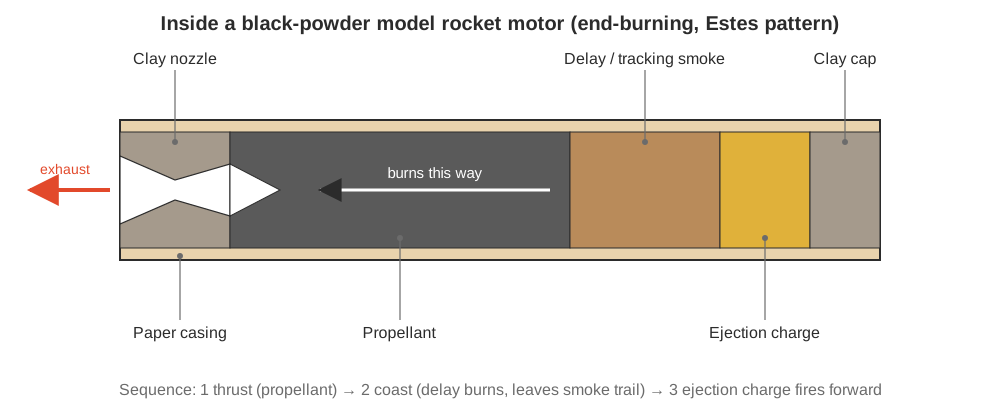
The whole motor is a timed sequence: thrust → coast → eject. On an ordinary motor the flyer cannot change that sequence, only pick a motor whose numbers fit the rocket. Electronic deployment, where an altimeter fires the charge at apogee whatever the motor’s delay, is the subject of the Payload Electronics and Recovery dives.
A motor is ignited electrically. A small igniter goes into the nozzle: a short loop of resistance wire coated with a pyrogen bead, held in place with a plastic plug. The launch controller passes enough current through it to heat the wire and light the bead, and the bead lights the propellant. Igniters, controllers and launch pads have their own dive: Launchers.
1.3.2 Reading the motor code
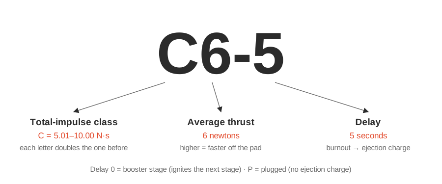
Every certified motor carries a code such as C6-5 (Figure 3). The code has three parts:
- The letter is the total-impulse class: how much push the motor delivers in all, in newton-seconds (N·s). Each letter allows twice the total impulse of the one before it, so a C motor can deliver up to twice the impulse of a B and four times that of an A.
- The first number is the average thrust in newtons. A C6 averages 6 N over its burn. For the same letter, a higher number means a harder, shorter push. A heavy rocket needs this to get off the rod quickly.
- The number after the dash is the delay in seconds, from burnout to ejection. A light rocket that coasts a long way needs a long delay. A heavy or draggy one needs a short delay, so the parachute comes out near the top and not on the way down.
Two special delays appear in the catalog:
- Delay 0 (A10-0, B6-0, C6-0) means the ejection charge fires the instant the propellant burns out. These are booster motors for the lower stage of a multi-stage rocket. The ejection blast lights the next stage’s motor. A -0 motor in a single-stage rocket deploys at full speed, low in the flight, and usually shreds the parachute.
- P (D12-P, A10-PT) means plugged: no delay and no ejection charge at all. Plugged motors are for rocket gliders, radio-controlled rocket gliders and rockets with their own electronic deployment.
A trailing T on Estes mini motors (A3-4T, A10-PT) marks the 13 mm “tiny” size.
1.3.3 The impulse classes
The total-impulse classes double from one letter to the next:
Table 2 — The total-impulse classes double from one letter to the next
| Class | Total impulse (N·s) | Where it sits |
|---|---|---|
| 1/4A | 0.00–0.625 | Mini motors; first flights in small fields |
| 1/2A | 0.626–1.25 | Mini motors |
| A | 1.26–2.50 | The smallest “standard” motors |
| B | 2.51–5.00 | Most first flights of a standard kit |
| C | 5.01–10.00 | The most popular sport motor |
| D | 10.01–20.00 | 18 mm composite or 24 mm black powder |
| E | 20.01–40.00 | Large model rockets |
| F | 40.01–80.00 | Composite motors |
| G | 80.01–160.00 | The largest single model-rocket motor |
| H and up | 160.01 and up | High power: certification required |
The model-rocket limit of 320 N·s is the installed total. A rocket can therefore cluster or stage up to the equivalent of two G motors and still be a model rocket. A single H motor (160.01–320 N·s) is in the same impulse range, but in the United States it is classed as high power, and buying or flying one needs certification. The H boundary is the subject of the High-Power Rockets dive.
1.3.4 Sizes
Motors come in standard diameters so that any certified motor of the right size fits any rocket built for it. The Estes black-powder line has three:
- 13 mm “mini” motors, about 45 mm long (1/4A3-3T, 1/2A3-4T, A3-4T, A10-PT).
- 18 mm “standard” motors, about 70 mm long. These are the A8, B4, B6 and C6 family, which most kits are built around.
- 24 mm motors: the D12 and C11 at the same 70 mm length, and the longer E9 and E12 at about 95 mm.
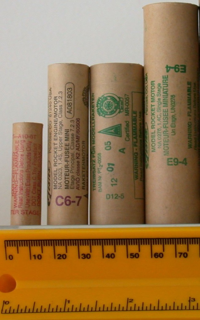
Composite motors (ammonium-perchlorate propellant, as in the Aerotech, Cesaroni and Quest lines) add the 29 mm size and pack more impulse into a given casing. An 18 mm composite can be a D, the same class as a 24 mm black-powder D12. Adapters let a smaller motor fly in a larger mount (13→18, 18→24, 24→29 mm). An adapter has to be fitted with its own motor hook or retention, or the motor will be ejected out of the back.
1.3.5 Choosing a motor for a kit
The short version, until the Motors dive covers the details:
- Use the motors the kit recommends. Every kit’s instructions list the motors its maker has flown it on, and the delays that suit its weight and drag. A motor off the list is a guess.
- Make the first flight on the smallest recommended motor. A new rocket’s first flight tests the build: fin alignment, nose fit, chute packing, ejection. It should do that at a height where it is easy to follow and lands close by.
- Respect the maximum liftoff weight. Each motor has a maximum recommended liftoff weight. A heavy rocket on a low-thrust motor leaves the rod too slowly for its fins to work, and it turns into the wind or arcs over. A common rule of thumb is a thrust-to-weight ratio of at least 5:1 off the rod.
- Match the delay to the rocket. Pick a shorter delay for heavier or draggier rockets and a longer one for light, slick rockets. The aim is ejection at or just after apogee, when the rocket is moving most slowly. A simulator such as RockSim or OpenRocket predicts the best delay before the first flight (the RockSim dive shows how).
1.4 Stability: why a rocket flies straight
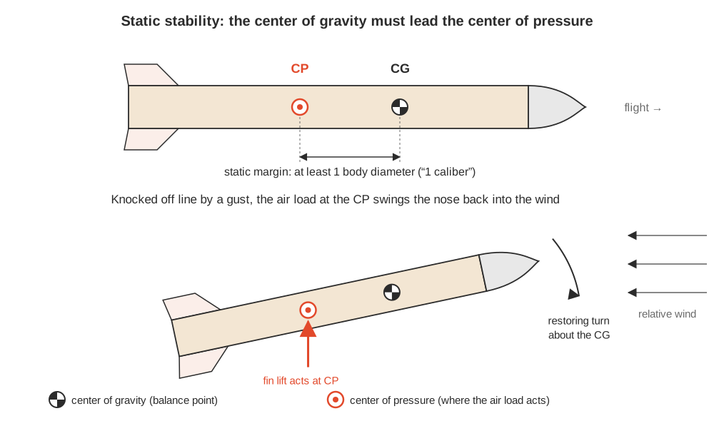
A model rocket has no guidance system, gyroscope or moving surface. It flies straight because of where two points sit along its length (Figure 5):
- the center of gravity (CG), the balance point, where the rocket’s weight acts; and
- the center of pressure (CP), the point where the sum of all the aerodynamic side-forces on the rocket acts when it is at an angle to the airflow.
A rocket is statically stable when its CG is ahead of (nearer the nose than) its CP. When a gust or a crooked launch tips the rocket at an angle to its line of flight, the air pushes sideways on the body and fins. The fins are at the back, so the CP sits aft, and the resulting push swings the tail back behind the nose, like the feathers on an arrow or a weathervane turning into the wind. If the CP is ahead of the CG, the same push swings the tail forward, and the rocket tumbles, loops or corkscrews.
1.4.1 The one-caliber rule
The distance from CG to CP, divided by the body diameter, is the static margin in calibers. The hobby’s rule of thumb is at least one caliber (CG at least one body diameter ahead of CP), and up to about two for a typical sport rocket.
- Too little margin (under about one caliber) means the rocket corrects slowly or not at all. It wobbles, and in a gust it can go unstable.
- Too much margin (a heavy nose and big fins: “over-stable”) means it weathercocks hard. It turns sharply into any wind off the rod and flies a low, upwind arc. It is safe, but it loses height and comes down a long way upwind.
Static margin moves during a flight. As the propellant burns, the CG moves forward (the tail gets lighter), so margin usually increases after liftoff. Checking stability with the motor installed gives the worst case.
1.4.2 Finding the CP: Barrowman, cutouts and swing tests
The CG is easy to find: balance the rocket, with the motor and recovery system installed, on a finger or a knife edge and mark the point. The CP is harder, and the hobby has used three methods to find it.
The cardboard cutout. The oldest method is to trace the rocket’s side silhouette on card, cut it out and balance it. The balance point of the cutout, its area centroid, approximates the CP. This is conservative: it puts the CP further forward than it really is, because it treats the nose cone and body as if they produced as much side-force per square inch as the fins. A rocket that passes the cutout test is almost always stable.
The Barrowman equations. In 1966 James and Judith Barrowman produced The Theoretical Prediction of the Center of Pressure, a research report presented at NARAM-8, the NAR’s national meet, on 18 August 1966. It derived simple subsonic equations for the CP of a nose, body transitions and a fin set, built on linearized flow theory. An ordinary modeller could work them by hand from the rocket’s dimensions. They made it possible to design a stable rocket on paper, before cutting any balsa, and they are still the core of every rocket design program. The equations assume small angles of attack and subsonic speed. They become less accurate approaching Mach 0.7, and they ignore the side-force from the body tube itself, which matters at high angles of attack. Later work extended them, but for any kit rocket they are accurate enough.
The swing test. The field check is to tie a string around the rocket at its CG, with the motor installed, tape it so it hangs level, and swing it in a circle overhead. A stable rocket points its nose into the circle of travel. An unstable one wobbles or flies tail-first. The test is crude: the swinging airflow is curved, and a marginal rocket can pass or fail depending on the swing. But it needs nothing but string. A rocket that will not fly nose-first on a string will not fly nose-first off a pad.
Today the CP is found by software. RockSim (Tim Van Milligan’s program from Apogee Components) and the free OpenRocket both apply the Barrowman method, with corrections, to a drawn model. They display CG and CP on the drawing, give the static margin in calibers, and fly a simulated flight. The RockSim dive covers designing, simulating and checking a rocket in RockSim Pro. Van Milligan’s Peak of Flight newsletter from Apogee has covered stability, CP and simulation in depth for years; I have read nearly every issue.
1.4.3 Fixing an unstable rocket
There are two ways to move CG ahead of CP:
- Move the CG forward by adding nose weight: modelling clay pressed into a plastic cone’s shoulder, or a lead or steel weight epoxied into a balsa one. This is the usual fix for a rocket that has picked up weight in the tail, from a heavier motor or a camera.
- Move the CP aft with larger fins, fins set further back, or fins swept back so their area sits further aft.
Nose weight costs height. A larger fin costs drag. Both are cheaper than a lost rocket.
1.5 The flight, stage by stage
Figure 6 follows a single-stage flight from the push of the button to landing.
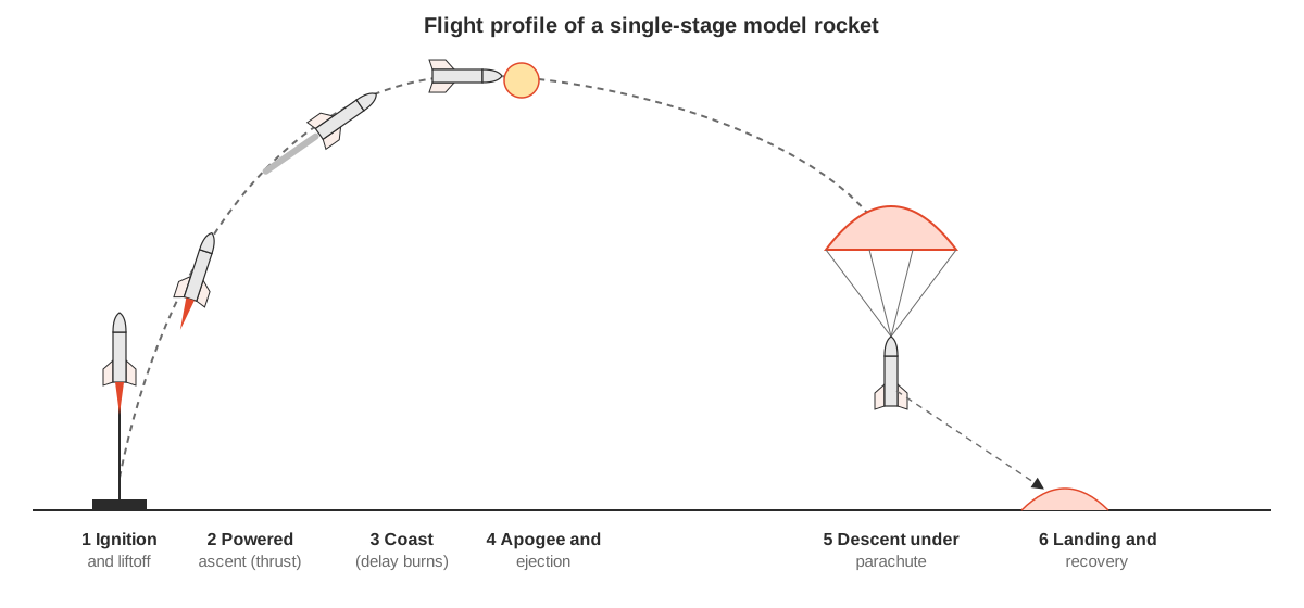
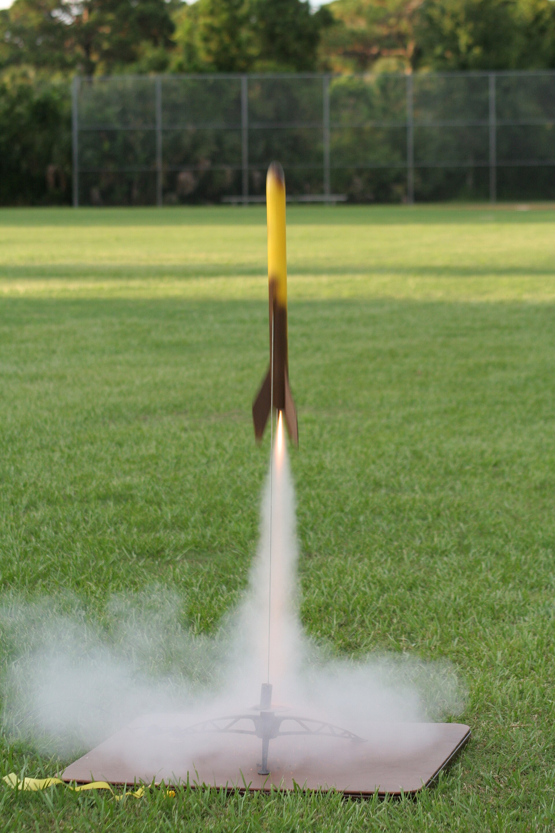
- Ignition and liftoff. The controller’s launch button sends current through the igniter. The propellant lights within a fraction of a second, and the rocket slides up the launch rod. The rod holds it on line for the first metre or so, until it is moving fast enough for the fins to keep it pointed.
- Powered ascent. The motor burns, usually for between half a second and two seconds for an A–C black-powder motor. The rocket accelerates hard: the peak thrust of a C6 is more than twice its average, and a small rocket reaches high speed within a few metres. Nearly all of the rocket’s speed is gained in this stage.
- Coast. At burnout the rocket is at its fastest and keeps climbing on momentum, slowed by gravity and drag. The delay element burns, trailing smoke. Most of the rocket’s height is gained in this stage. On a light rocket it can last longer than the burn.
- Apogee and ejection. The rocket slows to a near-stop at the top of its arc, its apogee. If the delay is right, the ejection charge fires at or just after this moment. The charge pushes out the wadding, parachute and nose cone. If ejection is too early, the rocket is still fast and the snatch can tear the shock cord or “zipper” the body tube. If it is too late, the rocket has nosed over and is diving, and the chute has to open at speed.
- Descent. The parachute or streamer opens and lowers the rocket, its nose cone and the spent motor together on the shock cord. A typical descent rate is 3–5 m/s (10–15 ft/s). The wind drifts the rocket downwind the whole way down. That is why small fields call for smaller motors, streamers and reefed or spill-holed parachutes.
- Landing and recovery. The rocket lands, the flyer walks out to collect it, and back at the bench it gets a new motor, fresh wadding and a re-packed chute, ready to fly again.
1.5.1 Weathercocking
A stable rocket turns into the relative wind, the airflow it feels. At liftoff that airflow combines the rocket’s upward speed with any crosswind. A slow rocket in a stiff breeze sees air coming partly from the side and turns upwind. This is weathercocking: the same stability that keeps the rocket straight makes it lean into the wind.
The usual fixes are a motor with higher average thrust (often a composite), a longer rod or a rail, and a lighter rocket. The safety code limits how far a rod may be tilted from vertical.
1.6 Recovery in one page
Recovery has its own dive. The basic choices, by what the ejection charge releases:
- Parachute. A plastic or nylon canopy on shroud lines, packed above the wadding. It is the standard for anything heavier than a few dozen grams. A spill hole in the canopy or a reefed (partly tied) canopy speeds the descent and cuts wind drift.
- Streamer. A long ribbon of crepe paper, plastic or Mylar. It flutters, adds drag and brings a light rocket down faster than a chute, with much less drift. It suits small rockets in small fields.
- Featherweight or tumble recovery. The ejection charge pushes the motor out of the back, or shifts the CG, so the rocket becomes unstable and tumbles down slowly. It is used for very light rockets.
- Nose-blow or separation. The rocket separates into pieces that each come down on their own small chute or streamer.
- Glide. Rocket gliders boost on a pod and glide down. Boost gliders drop the pod and glide; radio-controlled gliders are flown back.
- Helicopter. Blades deploy at ejection and autorotate the rocket down.
On larger rockets, an altimeter fires the deployment charges instead of the motor’s delay. It fires a drogue at apogee and the main parachute low, close to the ground. This dual deployment is covered in the Payload Electronics and Recovery dives.
1.7 Launching in one page
A model rocket is launched electrically and remotely, from a launch pad and a launch controller:
- The pad holds a launch rod (or, for heavier rockets, a rail) vertical. It has a blast deflector, a metal plate that turns the exhaust away from the ground and the pad legs. The rod tip should be capped, or kept above eye height, when no rocket is on it.
- The controller is a battery box with a long cable to clips on the igniter. It has a removable safety key, so it cannot fire while someone is at the pad. It has a continuity light, which shows that the igniter circuit is complete when the key is in. And it has a spring-loaded launch button that returns to off when released.
I designed and built my first launch controller when I was about eleven.
Pads, rails, controllers, relay boxes, club-style launch racks and the wiring that makes a dozen pads safe are the Launchers dive.
1.8 The safety code, briefly
The NAR Model Rocket Safety Code is short, and every kit prints a copy. Its main points:
- Use only certified commercial motors, and never alter them or use them for anything else.
- Use an electrical launch system with a removable safety interlock and a launch switch that returns to off. Count down before launch.
- After a misfire, remove the safety key and wait 60 seconds before approaching the pad.
- Stand back: the code sets a minimum distance from the pad, at least 15 ft (5 m) for D and smaller motors and 30 ft (9 m) for larger ones.
- Launch within 30° of vertical, never at a target, and not in winds above 20 mph (32 km/h).
- Respect the size limits (1,500 g, 125 g of propellant, 320 N·s) and fly from a field at least as large as the code’s site-size table specifies for the motor.
- Never try to recover a rocket from a power line, a tall tree or another dangerous place.
The code is revised from time to time. The current version, with its full launch-site dimension table, is the one on nar.org, and that version takes precedence over any summary, including this one.
1.9 Where this volume hands off
The next volume in this dive takes a kit from the box to the field: tools, glues, motor-mount assembly, fins (cutting, sanding, gluing, fillets), the shock-cord mount, a first finish and a first flight. Among the kits are the ones I built more than once: the Mars Snooper, Mars Lander, Andromeda, Saturn V and Mega Der Red Max.
After that, the deeper subjects each have their own dive:
Table 3 — After that, the deeper subjects each have their own dive
| Dive | What it covers |
|---|---|
| History | From Carlisle, Stine and Estes in the 1950s through Centuri, the space-age kits, composite motors, high power and the electronics era |
| Motors | Black-powder and single-use composite motors, how they work and how to choose and buy them; then high-power reloadable and buildable motors |
| Launchers | Pads, rods and rails, igniters, controllers and club launch systems |
| Recovery | Parachutes, streamers and other devices; sizing; packing; dual deployment |
| Payload Electronics | From film cameras to digital video, altimeters, deployment controllers, GPS and telemetry |
| High-Power Rockets | Larger airframes, certification, high-power motors and range rules |
| RockSim | Designing, simulating and checking a rocket in RockSim Pro |
| Jigs and Finishing | Fin jigs, tube marking, fillets, filling, priming, painting, decals and clear coat |
Sources
- National Association of Rocketry, Model Rocket Safety Code — https://nar.org/ModelRocketSafetyCode (the current text; summarized here, not quoted).
- U.S. Code of Federal Regulations, 14 CFR 101.22, Definitions (Class 1 model rocket) — https://www.ecfr.gov/current/title-14/chapter-I/subchapter-F/part-101/subpart-C/section-101.22.
- Federal Register, vol. 59, no. 190 (3 October 1994), final rule raising the model-rocket limits to 1,500 g and 125 g — https://www.govinfo.gov/content/pkg/FR-1994-10-03/html/94-24217.htm.
- Barrowman, James and Judith, The Theoretical Prediction of the Center of Pressure, NARAM-8 R&D report, 18 August 1966 — Museum of Flight archive record, https://archives.museumofflight.org/repositories/2/resources/579.
- Estes Industries, C6-5 product page (10 N·s total impulse, 6 N average thrust, 5 s delay) — https://estesrockets.com/products/c6-5-engines.
- OpenRocket component database, Estes sizes and part numbers (body-tube dimensions) — https://github.com/RogueRocketeer/OpenRocket-Database/blob/master/docs/estes_sizes_and_part_numbers.md.
- NSW Rocketry Association, Rocket resources (body-tube table) — https://nswrocketry.org.au/rocket-resources/.
- Wikipedia, Model rocket and Orville Carlisle (founding dates, for orientation only; the History dive works from primary sources).