Launchers · Volume 1
RELAY-6: A Six-Pad Wireless Launcher
An open design for a two-way, licence-free LoRa launch system: one RELAY-6 pad box at the rack and three interchangeable controllers (HALO, FLIGHTDECK and MONOLITH), with authenticated packets, a hardware watchdog, a per-pad igniter ohmmeter and ignition timer, a priced bill of materials, thirteen gated build stages and full-size cut sheets
Introduction
I designed and built my first launch controller when I was about eleven. It was built into one of my dad’s old tube caddies. It had six pads and a long run of wire, for which I used rotator cable, the multi-conductor cable that runs to an antenna rotator. A six-position rotary switch chose the pad, one at a time. Light bulbs showed continuity, a small key switch armed it, and a big button launched.
The next launcher I made used an old garage-door opener to fire a single pad without wires. It was not too safe, and it would sometimes go off on its own.
That second launcher is the reason for most of what follows. A garage-door receiver listens for a code that is easy to receive by accident: a neighbour’s remote, a burst of interference or a corrupted signal can open the door, or, in this case, light a motor. The design in this volume keeps what the first launcher got right (a key in series with the fire circuit, a check of every igniter before launch, one button that has to be pressed on purpose) and fixes what the second got wrong. Every radio packet is checked for corruption, then checked again with a cryptographic tag that only the paired controller can make. If the pad box hears nothing valid for one second, it disarms itself in hardware.
Status, November 2026: designed on paper, with Revision A firmware written and tested on a PC. Nothing has been bought, built or flown yet, the firmware has not run on real hardware, and every test gate below is still open. This volume is the Revision A design and build guide. The volume will gain photographs, measured numbers and a build log as the hardware is made.
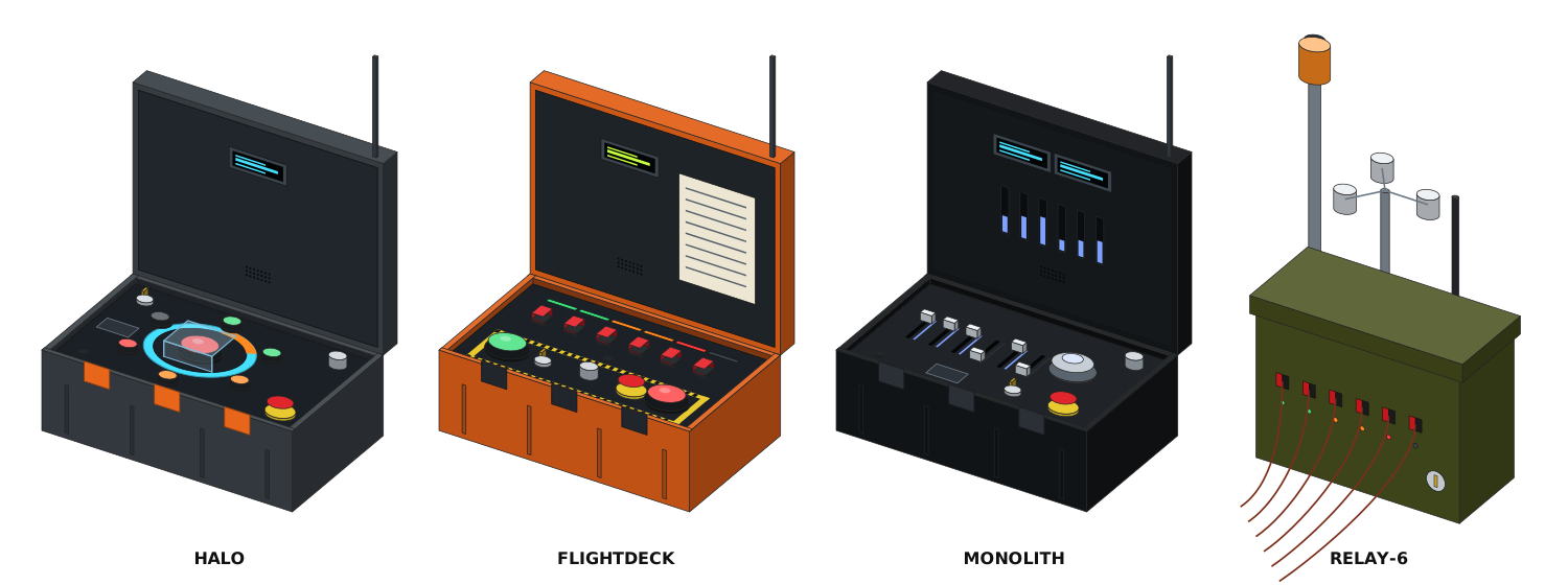
RELAY-6 has two kinds of unit. The RELAY-6 pad box sits at the launch rack, holds the battery and switches the igniter current to up to six pads. A controller, carried back to the flight line, sends requests over the radio and shows what the pad box reports. There are three controller designs, HALO, FLIGHTDECK and MONOLITH. They share one electronics core and differ only in their panels and cases. Any of the three pairs with the pad box.
The full build pack (the 37-page printed guide, the priced bill of materials, the 1:1 cut sheets and the DXF cut files) is published with this volume. The links are in Printable files and Printable Bill of Materials.
1.1 Why wireless
A wired launch controller is a battery, a key, a button and a long pair of wires. The wire is the weak point. A long, thin lead loses part of the battery’s voltage before it reaches the igniter, and thirty metres of it has to be unreeled, walked over and reeled in again.
A wireless system moves the battery and the switching out to the rack and replaces the long wire with a radio link. That buys three things:
- No long lead. The pad leads are a few metres of heavy zip cord from the pad box to the clips.
- Full battery voltage at the igniter. The current flows only through those short, heavy leads, so a cluster of several igniters on one pad, or a high-current igniter for a high-power motor, gets the current it needs.
- The pad box can measure and report. It can measure each igniter’s resistance before launch, time how long each one takes to burn through, read the wind and the battery, and send all of it back to the operator.
It also brings the problem the garage-door launcher had: a radio receiver will hear things it was not meant to. Most of the design effort goes into making sure the pad box acts only on packets that its own controller sent, recently, in the right order.
Three published designs fed this one. Altus Metrum’s TeleLaunch (TeleLCO controller and TeleFireEight pad boxes, by Bdale Garbee and Keith Packard) is a two-way digital system on the 70 cm amateur band, with AES-authenticated packets, a key at each end, a 100 µA continuity check and drag-race selection. Edward Robinson’s Overkill Model Rocket Launch Controller (Instructables and YouTube, 2020) put an Arduino Mega, an NRF24 radio and an LCD into a briefcase-style case with security codes, a 15-second countdown, a wired backup igniter circuit and a big emergency stop. RELAY-6 takes the authenticated link, the two keys and the continuity check from TeleLaunch, and the case, the panel, the countdown and the emergency stop from the Overkill controller, and adds an igniter ohmmeter, an ignition timer, a wind lock-out, a spoken countdown and NFC arming.
1.2 The system
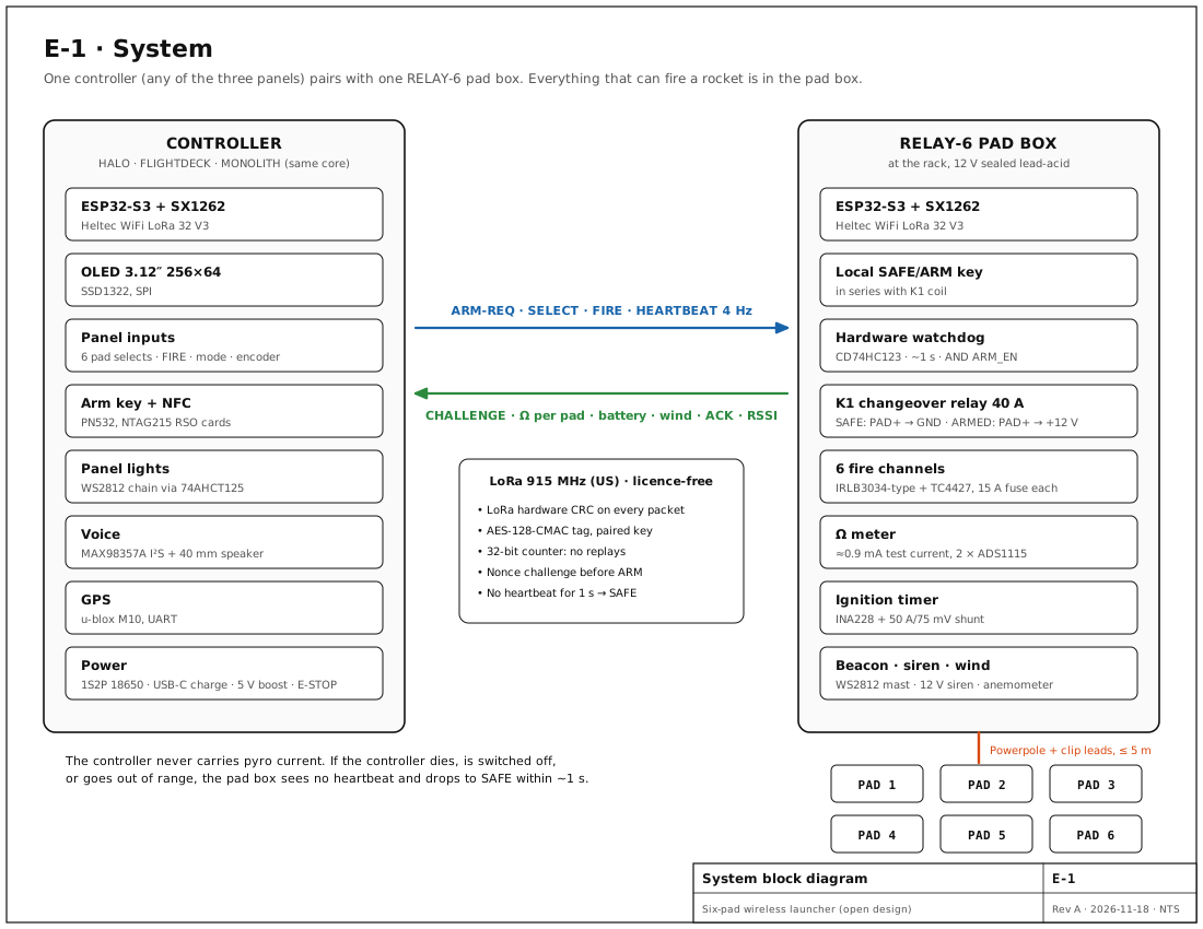
Table 1 — The system
| Unit | What it does | Case |
|---|---|---|
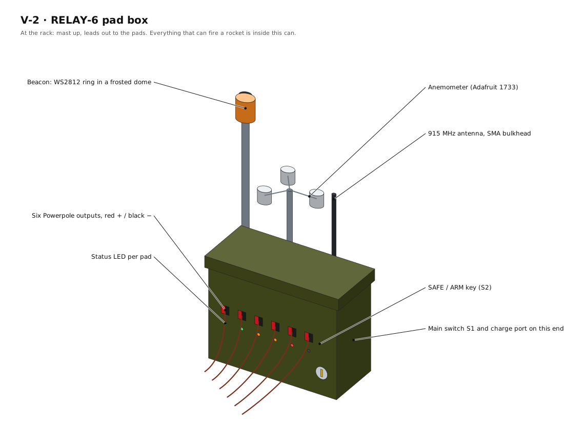
| RELAY-6 pad box | Six fire channels (40 A-class MOSFETs), a changeover relay that grounds the igniter bus when safe, a local arm key, a hardware watchdog, the igniter resistance meter, the ignition timer, a beacon, a siren and an anemometer | .50 cal steel ammo can |
| HALO | Six lit pad keys in a ring around a covered FIRE button, inside an edge-lit acrylic halo that drains as the count runs | Harbor Freight Apache 3800, black |
| FLIGHTDECK | Six toggle switches under red flip covers, a two-hand fire zone (ARM left, FIRE right) and a backlit checklist in the lid | Harbor Freight Apache 3800, orange |
| MONOLITH | Six slide levers pushed forward to commit a pad, a twist-collar fire core and a twin-OLED strip in the lid | Harbor Freight Apache 3800, black |
The Apache 3800 is Harbor Freight’s copy of the Pelican 1450 size of hard case: the “Pelican-style knock-off” of the brief.
1.2.1 Key numbers
Table 2 — Key numbers
| Pads | 6 per pad box; the protocol carries a bank number so a second box can join later |
| Fire modes | Single · Select (any set) · Salvo (all six) · Ripple (0.25–5 s steps) · Drag race |
| Pyro supply | 12 V sealed lead-acid, 7.2 Ah (as TeleLaunch uses); 40 A main fuse; 15 A fuse per pad |
| Fire pulse | 1.0 s per pad (a firmware constant) |
| Igniter test current | About 0.9 mA (3.30 kΩ from a 3.0 V rail), in SAFE only |
| Radio | LoRa, 902–928 MHz ISM band (US), licence-free under FCC Part 15; 868 MHz build option for Europe |
| Link security | LoRa CRC + AES-128-CMAC tag + 32-bit counter + ARM nonce; 4 Hz heartbeat, 1 s fail-safe |
| Controller battery | 2 × 18650 cells in parallel (1S2P), USB-C charging |
1.2.2 Why LoRa, not the ham band
TeleLaunch runs on the 70 cm amateur band, which needs an amateur radio licence to operate. I hold one, but I chose licence-free LoRa for RELAY-6 so that others can build and use it. LoRa is a long-range, low-data-rate radio scheme sold on cheap modules for the 915 MHz ISM band in the US (868 MHz in Europe), where no licence is needed under FCC Part 15. The condition was that it had to be safe, with every message CRC-checked or something equivalent. The answer is in The radio link: the CRC catches damaged packets, and a cryptographic tag catches packets the system did not send.
1.3 Safety
This is a pyrotechnic firing system. The pad box is live whenever its battery is connected. Every bench stage of the build uses dummy loads (resistors or 12 V lamps), not igniters. Real igniters appear only at Stage 6, outdoors, with no motor; a motor appears only after commissioning.
1.3.1 Rules the design follows
The NAR Model Rocket Safety Code and the NAR and Tripoli high-power codes require an electrical launch system with a safety interlock in series with the launch switch, and a launch switch that returns to off when released. They also require a countdown, and a wait after a misfire before anyone approaches the pad. The wording, the misfire wait and the minimum distances are set by the current text of the code that applies to a launch, not by this volume, so check it.
RELAY-6 meets those rules like this:
- Interlock in series. The pad box key S2 is in series with the coil of the relay K1. With the key out, no current can reach the igniter bus. The controller key is a second, firmware interlock.
- Spring-return launch switch. Every FIRE control is momentary. Releasing it stops the count or the fire command.
- Fail-safe radio. The pad box drops to SAFE when it hears nothing valid for 1 s, in firmware and in hardware (the watchdog U2).
- Shorted when safe. At rest, K1 ties the igniter bus to ground, so stray voltage cannot appear across an igniter.
On top of the codes, the design sets these for itself:
- A removable key in series with the fire circuit at both ends.
- No arm without an acknowledgement from the pad box.
- The controller’s E-STOP removes its power in hardware, so the pad box loses the heartbeat and disarms.
- A pad that does not fire is reported at once, before anyone walks out.
1.3.2 Batteries
- A lead-acid battery can deliver hundreds of amps into a short. The 40 A main fuse F0 goes within 100 mm of the battery terminal, and the run from the battery to K1 is 12 AWG or heavier.
- The pad box is charged with a 12 V lead-acid smart charger, with the main switch S1 off.
- Why not LiFePO₄. Small 12 V LiFePO₄ packs carry a protection board that limits current; the 10 Ah ExpertPower pack priced for this design is rated 10 A continuous and 15 A for 10 s. A six-pad salvo or a high-power cluster can trip it and switch the whole pad box off at the moment of launch. LiFePO₄ is usable only with a protection board rated for 40 A pulses or more, and a LiFePO₄ charger (14.6 V).
- The controller’s 18650 cells come from a reputable cell seller, sit in a protected holder or behind a BMS, and are never left charging unattended.
1.3.3 Radio
The LoRa modules run in the 902–928 MHz band under FCC Part 15. Use the antenna type the module was sold with, and do not add an amplifier. Builders outside the US need the 868 MHz (or local) version of the modules and the region set in firmware. The firmware uses one 915 MHz channel at 500 kHz bandwidth (SF8), because FCC 15.247 asks a single-channel, non-hopping system in this band for at least 500 kHz of bandwidth. Check the rules that apply where you fly.
1.4 Theory of operation
1.4.1 What a launch system has to do
An igniter is a small resistive bridge, typically around an ohm, that heats a pyrogen until it lights the motor. Model-rocket igniters need a few amps for a fraction of a second; electric matches need less, but must have it reliably. A launch system therefore has three jobs:
- deliver a short pulse of high current to the chosen igniters and nowhere else;
- make certain that it cannot do so by accident; and
- tell the operator, before the button is pressed, whether each igniter is connected.
1.4.2 The pad box: power and arming
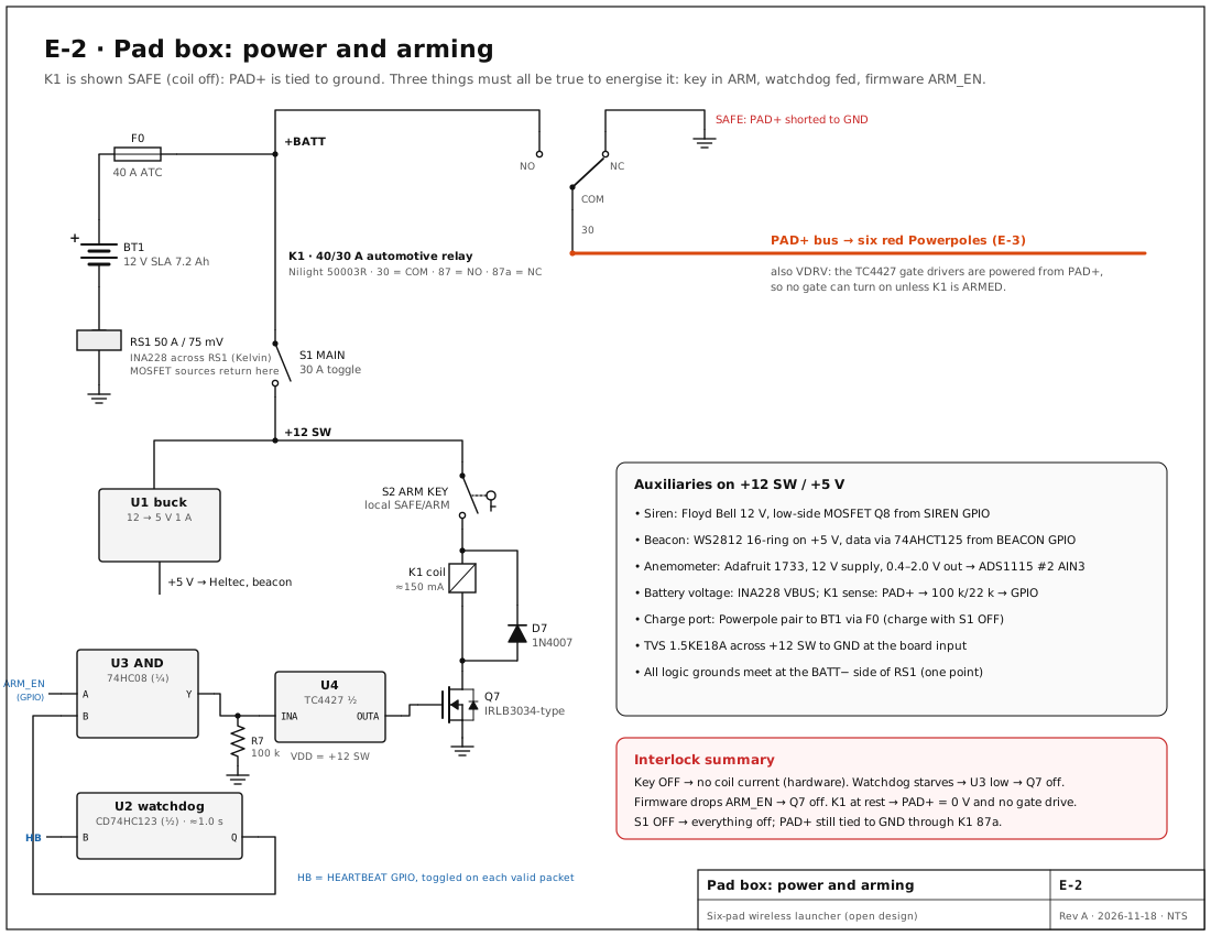
The battery feeds two paths through the 40 A main fuse F0. The logic path goes through the main switch S1 to a 5 V buck converter for the ESP32 board, the beacon and the sensors. The pyro path goes straight to the normally-open contact (87) of K1, a 40 A automotive changeover relay.
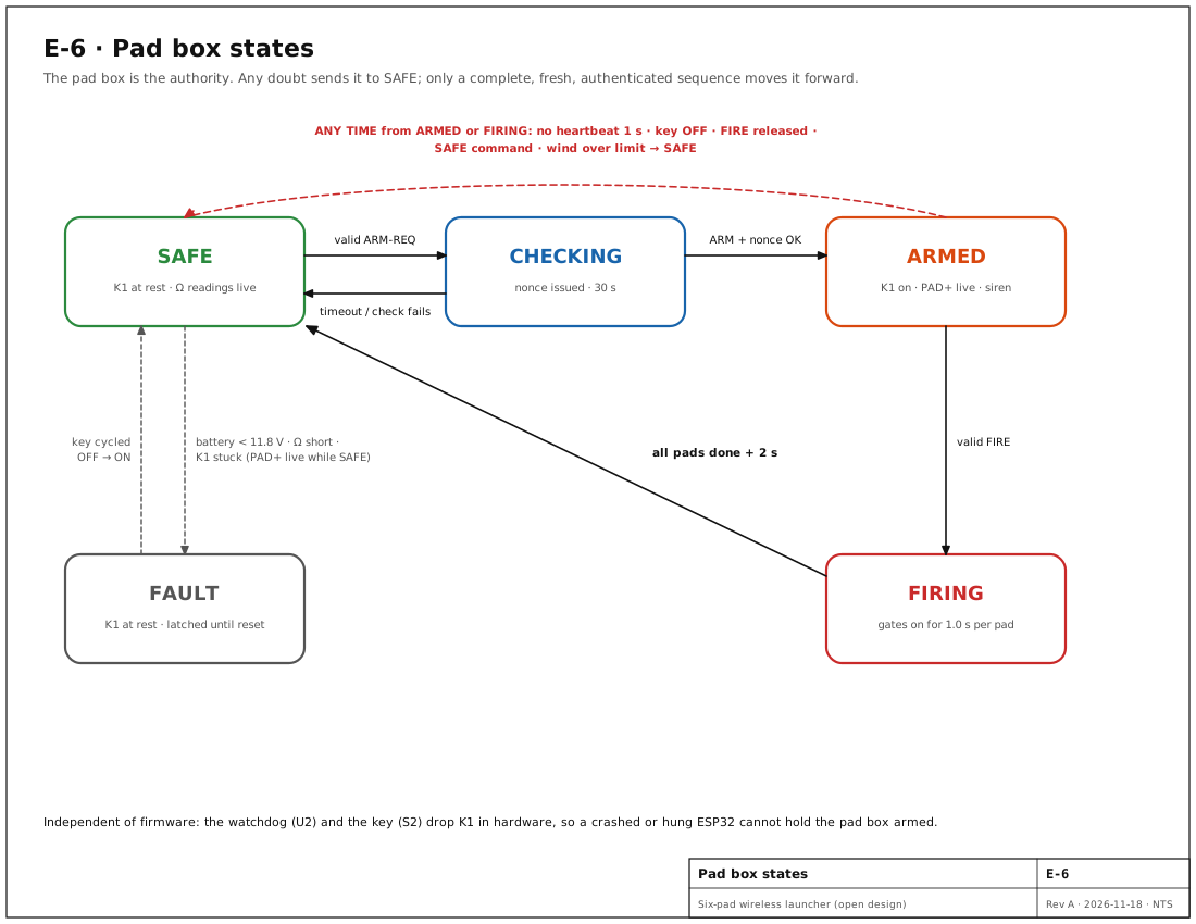
K1’s common terminal (30) is the igniter bus, PAD+. At rest K1 connects PAD+ to its normally-closed contact (87a), which is wired to ground. So in SAFE the bus is not merely switched off but tied to 0 V. When K1 pulls in, PAD+ moves to the battery. An automotive changeover relay breaks the first contact before it makes the second, so the battery is never shorted during the swap.
K1’s coil current flows through the arm key S2 and the MOSFET Q7. Q7 is driven by U4 (half a TC4427 gate driver) from the AND gate U3. One input of U3 is the firmware’s ARM_EN line. The other is the output of U2, a retriggerable monostable used as a hardware watchdog: the firmware toggles the HEARTBEAT line every time it receives a valid packet, and if the toggles stop for about a second, U2 times out and U3’s output falls no matter what the firmware is doing. The pad box can therefore be armed only while all three are true: the key is in ARM, the firmware asks for it, and valid packets are still arriving.
The six gate drivers that fire the pads are powered from PAD+. While K1 is at rest they have no supply and cannot turn a MOSFET on, so a firmware fault in SAFE cannot fire a pad.
1.4.3 One pad channel and the igniter meter
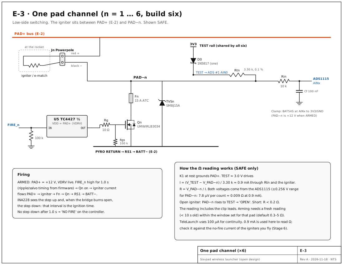
The igniter connects between PAD+ (red Powerpole) and its own return, PAD−n (black Powerpole). PAD−n runs through a 15 A fuse to the drain of an IRLB3034-type MOSFET, whose source returns to the battery through RS1, the current shunt. The Infineon IRLB3034 itself is out of production; the UMW UMWIRLB3034 is a current equivalent. To fire, the firmware raises FIRE_n; the gate driver lifts the gate to the 12 V of PAD+ and the MOSFET conducts. A 10 Ω gate resistor and a 100 kΩ pull-down keep the gate quiet, and an SMBJ15A transient suppressor clamps spikes picked up by the leads.
Resistance. In SAFE, PAD+ is grounded, so a small current fed into PAD−n flows through the igniter to ground. A Schottky diode from 3.3 V makes a shared TEST rail of about 3.0 V, and a 3.30 kΩ, 0.1 % resistor from TEST to each PAD−n sets about 0.9 mA. Two ADS1115 16-bit converters read TEST and each PAD−n. The firmware computes the current from the drop across the 3.30 kΩ resistor and divides it into the PAD−n voltage. On the ±0.256 V range one count is 7.8 µV, which at 0.9 mA is about 0.009 Ω. An open igniter lets PAD−n rise to TEST; a short reads near zero. The reading includes the clip leads, so it is taken with the leads that will be used. Arming needs a fresh reading (under 10 s old) inside the window set for that pad (by default 0.3–5 Ω).
TeleLaunch uses only 100 µA for its continuity check. RELAY-6 uses about nine times as much so that it can read ohms, not just “connected”. That current has to be far below the no-fire current of the igniters and e-matches in use, which is on the maker’s data sheet; it is an open item, checked before any igniter is connected.
Ignition time. An INA228 current monitor reads the shunt RS1. When a pad fires, the current steps up; when the bridge burns through, it steps down. The interval is reported as, for example, “lit in 184 ms”. A pad whose current never drops within the 1.0 s pulse is reported as NO FIRE at once, before anyone walks out to it.
1.4.4 The radio link
LoRa radios already add a CRC to every packet and discard any that arrive damaged. But a CRC proves only that a packet was not corrupted; anyone can compute one. So every packet also carries an 8-byte AES-128-CMAC tag, computed with a 16-byte key shared only by the paired controller and pad box, and a 32-bit counter that must always increase. A packet with a bad tag or an old counter is dropped without a reply.
- CRC vs CMAC. The CRC answers “did this packet arrive intact?”. The CMAC tag answers “did my paired partner make this packet?”. Stray RF, a neighbour’s remote or a corrupted packet cannot produce a valid tag without the key.
- Counter. Each sender’s counter is kept in flash and only goes up, even across a power cycle. The pad box rejects any counter it has already seen, so a recorded packet played back later is ignored.
- Nonce. Arming is a challenge and response. The pad box answers an ARM request with a fresh random 8-byte nonce, valid for 30 s, and accepts ARM and FIRE only if they carry that nonce under a valid tag. A recording of last week’s FIRE packet is useless.
- Heartbeat and watchdog. Both units send a heartbeat four times a second. If the pad box hears no valid packet for 1 s (four missed heartbeats), the firmware drops to SAFE, and the hardware watchdog U2 drops K1 whatever the firmware is doing.
- Pairing. A USB cable (or an NFC tap) writes a new random key into both units. There is no default key, and an unpaired unit will not arm.
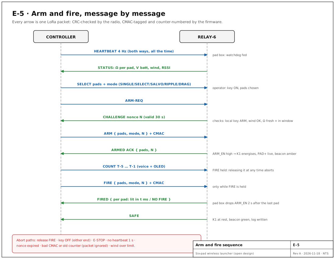
Each packet carries a 4-byte system ID (random, written at pairing), a bank number (1–99; 1 for a single pad box), a message type, the counter, up to 24 bytes of payload and the 8-byte tag; the radio adds its own 2-byte CRC. The message types are HEARTBEAT, STATUS (six resistances, battery, wind, RSSI, SNR, key state), SELECT, ARM_REQ, CHALLENGE, ARM (which can carry the RSO card’s ID), ARMED, FIRE, FIRED (six ignition times, or NO FIRE) and SAFE (with a reason code).
1.4.5 The controller
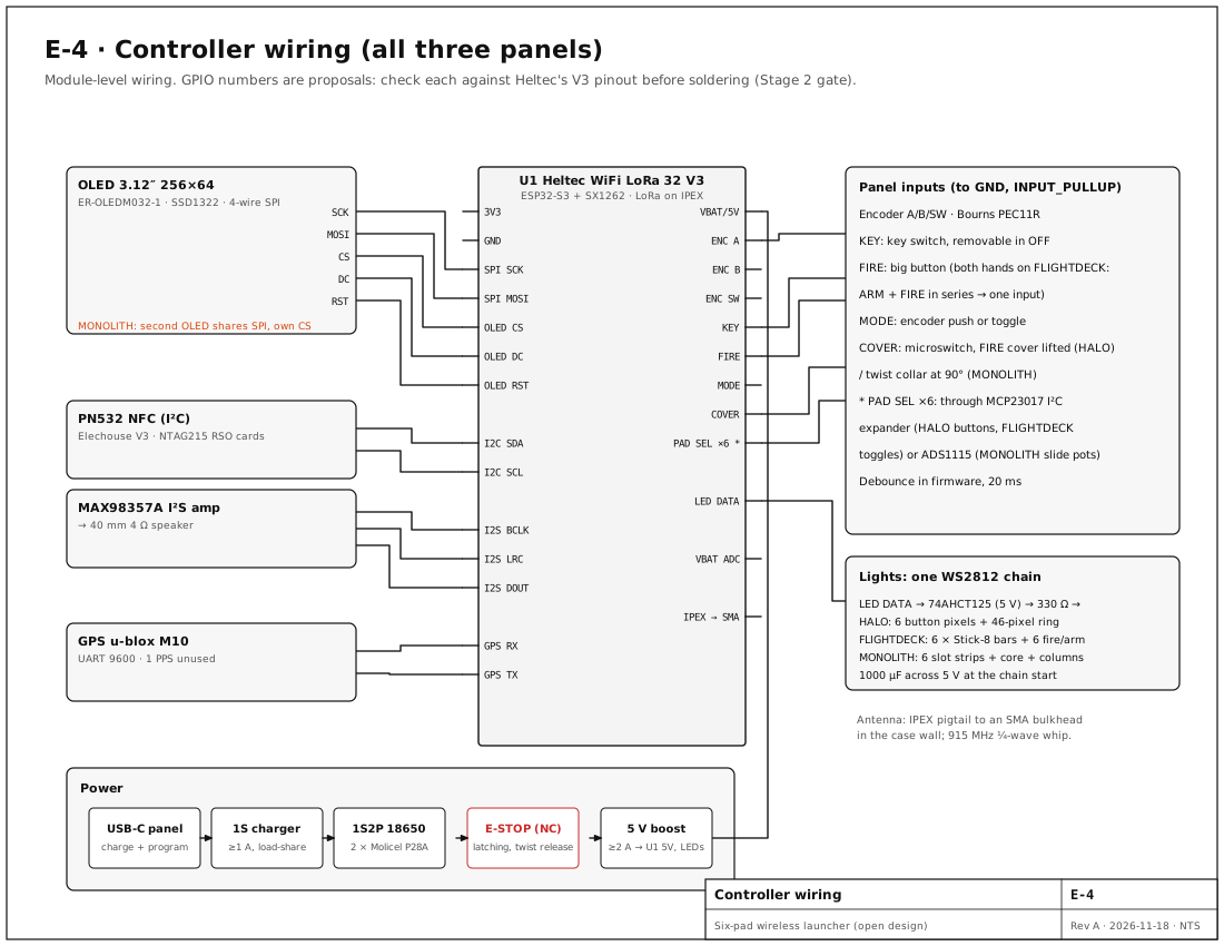
The controller is a Heltec WiFi LoRa 32 V3 (an ESP32-S3 with an SX1262 LoRa radio) plus:
- a 3.12-inch 256 × 64 OLED (SSD1322);
- a rotary encoder and a key switch;
- an NFC reader for the range-safety officer’s card;
- an I²S amplifier and speaker for the spoken countdown;
- a GPS for the flight log; and
- one chain of WS2812 LEDs for all the panel lights.
It runs from two 18650 cells in parallel through a USB-C charger and a 5 V boost converter. The E-STOP is in series with the battery: pressing it kills the controller, the pad box hears no heartbeat, and it drops to SAFE within a second.
1.4.6 Firmware
Both units run one firmware tree (PlatformIO, Arduino-ESP32, RadioLib for the SX1262), built for four roles: the pad box and the three controllers. The pad box firmware is the authority: it owns the state machine in Figure 6, and the controller can only ask.
The safety logic is kept apart from the hardware, in plain C++ with no Arduino code: AES-128 and CMAC, sealing and opening packets, both state machines, the igniter meter and the ignition timer. That lets it be tested on a PC. Revision A passes 71 checks there. They include the official AES and CMAC test vectors, tampered, replayed and reflected packets, and whole simulated launches between a controller and a pad box: a single pad, a ripple, a salvo, an igniter that never burns through, FIRE released during the count, the link lost while armed, the pad key pulled, a welded relay, and a replay of every packet from a recorded launch to a fresh pad box (nothing fires). The firmware also compiles for all four targets on the Heltec V3. It has not yet run on real hardware; build stages 1–5 are where it meets real boards.
Two details of the radio link. The pad box transmits only straight after it hears the controller, so the two ends never talk over each other. Arming happens only while FIRE is held: the controller sends ARM_REQ when FIRE is pressed, arms, counts, and fires, and letting go at any point sends SAFE. Porting to another radio board, such as an nRF52840 module with the same SX1262 radio, means changing only the radio and storage layer and the pin map.
The firmware, the drawing generators, the DXFs and the BOM are open source in one public repository, tjscientist-labs/RELAY-6 on GitHub, under the GNU General Public License, version 2 or any later version (GPL-2.0-or-later). The README there explains how to run the PC tests and build each of the four targets.
The firmware’s timing constants, as designed:
Table 3 — The firmware's timing constants, as designed
| Constant | Value | Why |
|---|---|---|
| Heartbeat interval | 250 ms | Four chances per second |
| Link-loss SAFE (firmware) | 1.0 s | Four missed heartbeats |
| Watchdog U2 (hardware) | 0.8–1.2 s, measured at Stage 3 | Backs up the firmware |
| Nonce lifetime | 30 s | Time to walk the key and call the range |
| Resistance reading, maximum age to arm | 10 s | Clips may be disturbed after the reading |
| Resistance window (default, per pad) | 0.3–5.0 Ω | Set per igniter type |
| Fire pulse | 1.0 s per pad | Long enough for model-rocket igniters; e-matches fire in milliseconds |
| Ripple step | 0.25–5.0 s | Operator’s choice |
| Countdown | 5 s, FIRE held | The safety codes call for a countdown |
| Wind lock-out | 20 mph gust | The NAR code’s wind limit for model rockets; set lower for the field |
| Battery low | 11.8 V at rest | Lead-acid about 20 % left |
| Link margin warning | SNR below 0 dB or RSSI below −110 dBm | Adjust after the range test |
1.5 The three controllers
All three controllers do the same things: select pads, choose a mode, arm, count down and fire. They differ in how the hands do it. I decided to build all three on the one shared core and pad box, so a builder can choose one and add the others later as new panels.
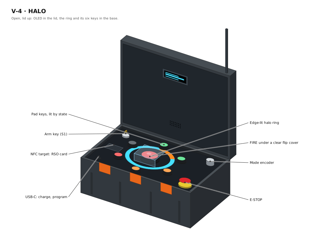
HALO is the simplest to build. The six 30 mm pad keys each carry a NeoPixel, so they light by state. The halo is a 6 mm clear acrylic ring sitting on four bridges over a WS2812 strip; the strip shines up through four arc slots in the panel. The 60 mm FIRE button sits under a hinged clear cover with a microswitch that tells the firmware when the cover is lifted. With the cover closed, FIRE does nothing.
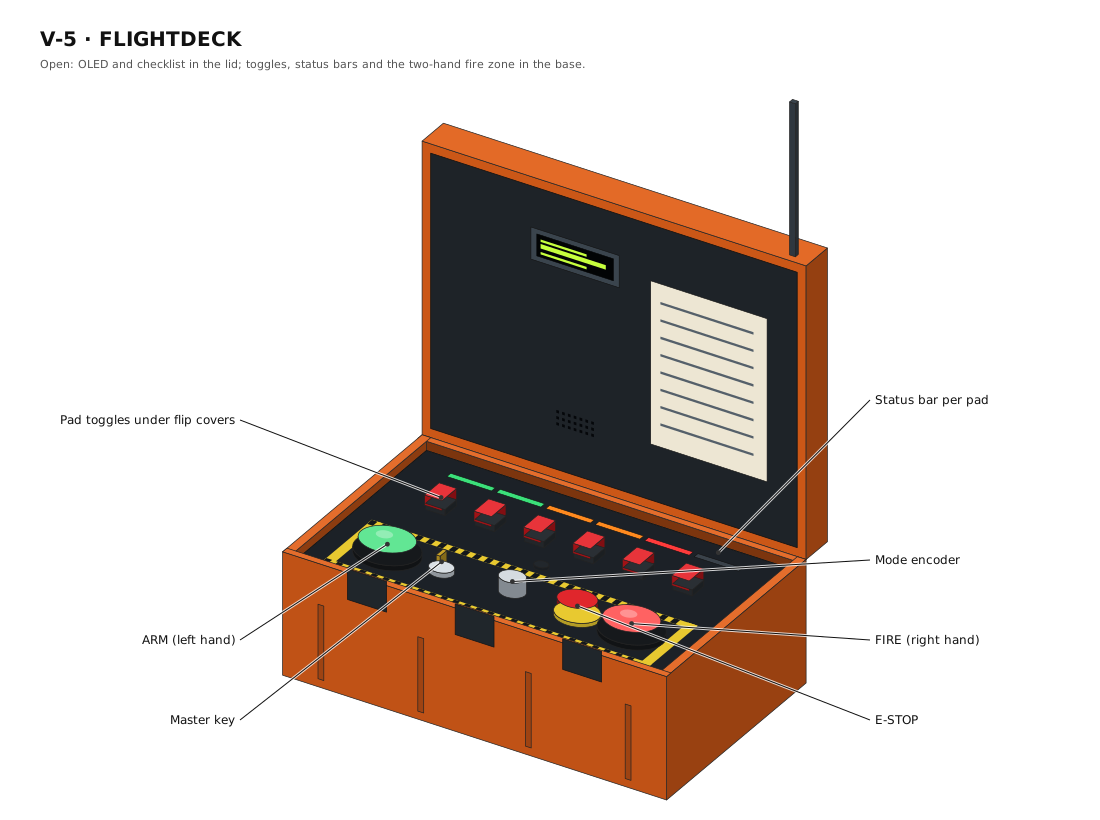
FLIGHTDECK is the cockpit. Lifting a red cover and flipping its toggle puts that pad in the selection. ARM and FIRE are 60 mm buttons 252 mm apart, wired in series into the one FIRE input, so it takes both hands to start a count and releasing either stops it. The panel is drawn for laser-cut, powder-coated 3.18 mm aluminium, or 3 mm acrylic for a first version.
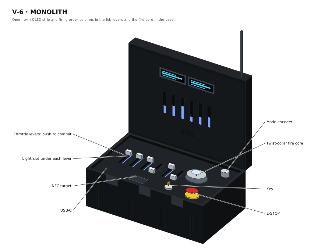
MONOLITH is the strangest. Each pad has a 60 mm slide potentiometer under a slot, read by an ADS1115; a lever in the top 10 % of its travel commits its pad. The fire core is a 30 mm illuminated button in the bore of a 6810 bearing. A printed collar on the bearing carries a cam that closes the cover microswitch at 90°, and a torsion spring returns it to safe from any angle. The panel is two layers of 3 mm black acrylic laminated together.
1.6 What it costs
Revision A was priced line by line on 18 November 2026, from the suppliers’ own pages: one unit of each part, before tax and shipping.
Table 4 — What it costs
| Build | Parts cost (USD) |
|---|---|
| Pad box (RELAY-6) | $632 |
| HALO controller (core + panel) | $430 |
| FLIGHTDECK controller | $527 |
| MONOLITH controller | $499 |
| Pad box + HALO | $1,062 |
| Pad box + all three controllers | $2,087 |
| Saving per controller without GPS and NFC (optional rows) | $87 |
The controller core is about $287 of each controller (of which $87 is optional), and the HALO, FLIGHTDECK and MONOLITH panel parts are about $142, $239 and $211.
Why it costs more than first guessed. The first rough estimate, made from the concept sketches, was about $670 for one controller and the pad box, and about $1,470 for all three. Pricing every line raised it, for three reasons:
- The GPS and NFC parts. The u-blox GPS breakout, its antenna, the PN532 reader and the cards add about $87 to every controller.
- Panel fabrication. Laser-cut acrylic and aluminium panels from a cutting service are carried as allowances ($45 for HALO, $95 for FLIGHTDECK, $55 for MONOLITH) until the DXFs are quoted.
- Multi-packs. Several lines can be bought only in packs: 50 alligator clips, 50 ft of wire, five relays, 25 Powerpole sets. The spares serve the other builds, but the first build pays for them.
Where the money goes, and how to spend less. The pad box is the largest item (about $630). The anemometer, siren, fuse block, battery and charger are about $180 of it. Leaving the GPS and NFC off a controller saves $87; the flight log then simply has no position and arming needs no card. The rugged 60 mm buttons, toggles and keylocks are where the feel is, and they are worth keeping.
Pricing changed the design. Several parts drawn in the concept turned out to be obsolete, too small or unavailable:
- MOSFET: the Infineon IRLB3034PBF is obsolete. The design uses the UMW UMWIRLB3034, with the Infineon IPP015N04NF2S as the alternate.
- K1: the Bosch relay first drawn is rated only 20/30 A, so K1 is a Nilight 40/30 A changeover relay.
- Battery: the 10 Ah LiFePO₄ pack’s protection board is rated 10 A continuous and 15 A for 10 s, so BT1 is a 12 V 7.2 Ah sealed lead-acid battery.
- Watchdog and AND gate: the 74LVC1G single-gate parts are surface-mount only, so they became the CD74HC123E and 74HC08 in DIP, for proto-board building.
- Mast: no hinge was found for a ½ in tube, so the beacon mast is two 12 in lengths that plug together.
1.7 Parts, by group
The table below is condensed: the main parts of each group, not every row. The full list, with every part number, supplier, price, alternate and a tick box for each, is the printable BOM.
Table 5 — Parts, by group
| Group | Main parts | Subtotal |
|---|---|---|
| Controller core (one per controller) | Heltec WiFi LoRa 32 V3 (915 MHz); ER-OLEDM032-1 3.12″ 256 × 64 SSD1322 OLED; SparkFun u-blox MAX-M10S GPS + active antenna (optional); Elechouse PN532 NFC reader + NTAG215 cards (optional); Adafruit MAX98357A I²S amplifier + 40 mm 4 Ω speaker; Bourns PEC11R encoder; C&K Y101132C203NQ key switch; 22 mm latching E-STOP; 2 × Molicel P28A 18650 cells; Adafruit bq24074 USB-C charger; Pololu 5 V boost; 915 MHz whip antenna; MCP23017 I/O expander | ≈ $287 (of which $87 optional) |
| HALO panel | Apache 3800 case (black); six 30 mm arcade buttons with NeoPixel PCBs; 60 mm red LED FIRE button; cover microswitch; ¼ in clear cast acrylic for the ring; WS2812 strip; laser-cut panels P-1 to P-3 | ≈ $142 |
| FLIGHTDECK panel | Apache 3800 case (orange); six IP56 toggles with red safety flip covers; 60 mm green ARM and red FIRE buttons; WS2812 status bars; laser-cut, powder-coated aluminium panel P-4; lid insert P-5; hazard-stripe tape | ≈ $239 |
| MONOLITH panel | Apache 3800 case (black); six 60 mm slide potentiometers and caps; ADS1115; 30 mm IP67 illuminated fire button; 6810 bearing for the twist collar; second OLED; WS2812 strip; laminated acrylic panels P-6, P-7; printed collar and cam | ≈ $196 |
| RELAY-6 pad box | Heltec V3; ten UMWIRLB3034 MOSFETs; four TC4427A gate drivers; Nilight 40/30 A changeover relays (5-pack); 2 × ADS1115; INA228 + 50 A / 75 mV shunt; CD74HC123E watchdog, 74HC08 AND gate; Blue Sea 6-circuit fuse block, 15 A pad fuses, 40 A main fuse; 12 V 7.2 Ah SLA + smart charger; Anderson Powerpole 30 A sets and panel clamps; Mueller BU-60 clips; 16 AWG zip cord; .50 cal ammo can; key switch; Adafruit anemometer; Floyd Bell siren; NeoPixel ring and acrylic dome beacon; 915 MHz 5 dBi antenna; aluminium mast tube | ≈ $631 |
Tools for the build: a temperature-controlled soldering iron (and a heavier iron or a torch for 12 AWG lugs); a multimeter; a current-limited bench supply to 2 A; a four-wire ohmmeter or a 0.1 % reference resistor for the meter calibration; step drills to 32 mm, 22 mm and 30 mm punches or hole saws and a 60 mm hole saw; a Powerpole crimper and a ratcheting crimper for 12–10 AWG ring lugs; access to a laser cutter or a cutting service for the panels; and a drill press for the ammo can.
1.8 The build, stage by stage
The build is split into thirteen stages, 0 to 12. Each ends in a gate: a test that has to pass before the next stage starts. The order puts every electrical risk on the bench first, with a current-limited supply and dummy loads, and only then puts the electronics in a case. Live igniters come late, and a motor comes last. Stages 0–6 are on the bench and prove the electronics; 7–8 put the pad box in its can; 9–11 build the three controllers, in any order; 12 is the field check.
The pad box comes first. It is the part that can fire a rocket, and it is the same for every controller.
Dimensions are millimetres unless marked. “CHECK” on a cut sheet means measure the part in hand before cutting its hole: hole sizes come from the makers’ drawings where they publish one, and are marked CHECK where they do not.
1.8.1 Stage 0: order and measure
Order the pad box and core parts and one controller’s panel parts, with two Heltec V3 boards per pair plus a spare. When the case arrives, measure its inside (length and width at the rim, depth of base and lid, corner radius, how far the gasket groove stands in), enter the numbers in the geometry file parts.py and regenerate: every panel outline, hole and DXF is drawn from those numbers. Measure every CHECK part and correct its hole.
Gate 0. Every CHECK (red) on P-1 to P-9 confirmed or changed; the panel outline fits the case with 1 mm clearance all round.
1.8.2 Stage 1: two radios talking
Flash both Heltec boards with a RadioLib “ping-pong” test at 915 MHz (or the local band), SF7/125 kHz, CRC on, antennas fitted before any transmission. Add the authentication layer (a test key, AES-128-CMAC over header and payload, the 8-byte tag and the 32-bit counter) and log every rejected packet with its reason. Then tamper: flip one payload bit (must fail the tag), replay a captured packet (must fail the counter), use a different key (must fail the tag).
Gate 1. 1,000 packets each way across the room with none rejected; every tamper test rejected; a power-cycled unit resumes with a higher counter (the counter is kept in flash).
1.8.3 Stage 2: controller core on the bench
On a full-size proto board: the Heltec V3 in sockets, the 74AHCT125 level shifter, the MCP23017 (or the ADS1115 for MONOLITH), and headers for the OLED, NFC reader, amplifier and GPS, wired per E-4. Check the proposed GPIO map against Heltec’s V3 pinout before soldering. Power it from the bench supply at 3.7 V, 1 A limit, through the boost converter, and bring up one module at a time: OLED test pattern, encoder counts, a card read, a WAV clip, a GPS fix outdoors, an 8-LED test strip.
Gate 2. Every module works together on the one board; current under 400 mA with the LEDs dim; the OLED draws the six screens from the concept sheet with test data.
1.8.4 Stage 3: pad box logic and watchdog
A second proto board carries the pad box’s Heltec V3, buck converter, U2, U3, U4 and Q7 per E-2, from a 12 V bench supply at 1 A limit. K1 is in its socket with nothing on its contacts yet. Set U2’s timing (start with 100 kΩ and 10 µF): toggle HEARTBEAT from a test sketch, stop, and measure how long U2’s output stays high after the last edge; adjust the capacitor until it is 0.8–1.2 s. Then run the truth table, key OFF/ON × ARM_EN low/high × heartbeat running/stopped: K1 must pull in only for ON + high + running. Finally, crash test: with K1 pulled in, hang the sketch in a loop; K1 must drop within the watchdog time.
Gate 3. All eight rows of the truth table correct; K1 drops on a firmware hang; with S1 off K1 cannot pull in.
1.8.5 Stage 4: six channels into dummy loads
Build the six channels per E-3 on the power board: the six MOSFETs on a common aluminium bar (with insulating pads), fuse holders, TVS diodes and gate drivers, with PAD+ and the return in 12 AWG and each channel in 14 AWG. Wire K1 (87 to the fused battery feed, 87a to ground, 30 to PAD+) and check, power off, that 30 reads 0 Ω to ground. Six 12 V 21 W lamps on the outputs, bench supply at 12 V and 10 A limit: arm and fire each pad, then a salvo; each lamp lights for 1.0 s only. With K1 at rest, command FIRE on every pad from the test sketch: nothing may light, because the gate drivers have no supply.
Gate 4. Every pad fires only when armed; no pad lights with K1 at rest whatever the firmware does; the MOSFET bar is warm at most after a six-lamp salvo.
1.8.6 Stage 5: igniter meter calibration
Fit the TEST rail, the six 3.30 kΩ resistors, the input resistors and clamps, and the two ADS1115s. Put 0.50 Ω, 1.00 Ω and 2.00 Ω reference resistors (0.1 %, or measured on a four-wire meter) on each pad in turn, and store a per-channel offset for lead and contact resistance in flash. An open circuit must read OPEN and a short below 0.2 Ω. Measure the actual test current with a meter in series: it should be close to 0.9 mA.
Gate 5. All six pads read the reference resistors within ±0.05 Ω; OPEN and SHORT detected.
1.8.7 Stage 6: real igniters, no motor
Outdoors, no motor, igniters only, standing well back as for a launch. Before connecting any igniter, confirm from its data sheet that the 0.9 mA test current is far below its no-fire current; if it is not, raise the 3.30 kΩ resistors and repeat Stage 5. With the battery in place of the bench supply and F0 fitted, fire each mode from the controller, then a three-igniter cluster on one pad, reading the current from the INA228 log.
Gate 6. Every igniter lit; every ignition time reported; no fuse blown; battery voltage recovers after a salvo; the INA228 log shows the salvo peak current, and the pad box stayed powered through it.
1.8.8 Stage 7: the pad box can
Tape the 1:1 templates P-8 (front) and P-9 (lid) to the can and centre-punch: six Powerpole outputs and the key on the front; the mast socket, antenna bulkhead and anemometer post on the lid; charge port and main switch on the end. Drill and punch, deburr, paint the inside of every hole against rust, and fit grommets and the cable gland. An inner plate of 6 mm plywood or HDPE carries the battery strap and both boards; the battery sits low and strapped, and nothing rests on it.
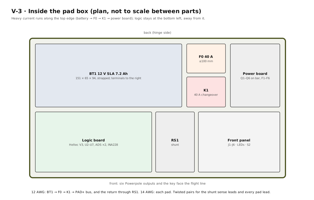
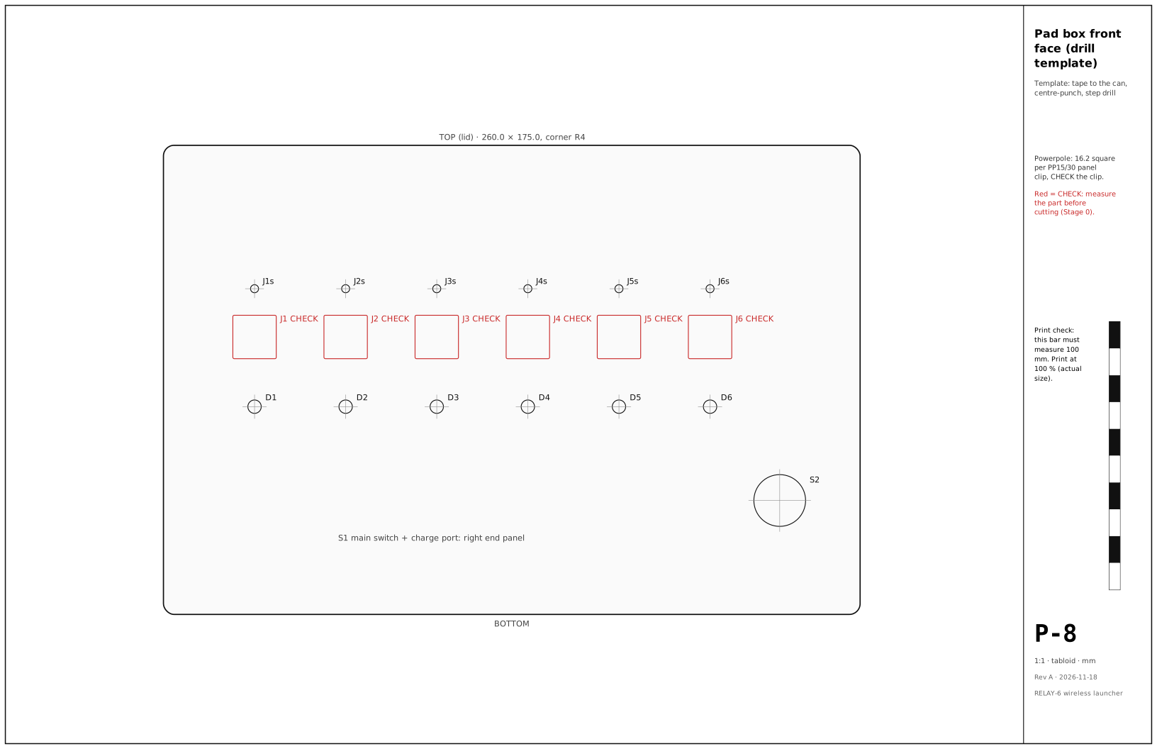
Gate 7. The lid closes over the wiring with the gasket seated; every hole is deburred and sealed; the board plate is fixed at four points.
1.8.9 Stage 8: pad box assembly
Move the boards into the can and re-run Gates 3, 4 and 5 there. Fit the beacon mast (two 12 in lengths of ½ in aluminium tube joined by a short internal coupler, plugged into the lid socket) and the anemometer, and check the wind reading against a hand anemometer or a weather report. Label every output 1–6, red +, black −, and the key positions SAFE and ARM.
Gate 8. Gates 3–5 pass again with the lid closed; the beacon is visible from 50 m in daylight.
1.8.10 Stage 9: HALO
Cut the panel (P-1, 3 mm black acrylic), the lid insert (P-2), and the ring, flip cover and hinge blocks (P-3). Sand the ring’s bottom face so it diffuses. Glue the WS2812 strip in a ring under the four arc slots, LEDs up, and bond the clear ring to the four bridges with acrylic cement. Fit the six 30 mm buttons with a NeoPixel PCB in each, the 60 mm FIRE button, the cover microswitch, key switch, E-STOP, encoder and NFC window. The panel sits on four standoffs with the core board under it; the OLED and speaker go in the lid and the antenna bulkhead in the case wall.
Gate 9. The ring lights evenly with no hot spots; FIRE does nothing with the cover closed; the full Stage 4 lamp test passes from the HALO.
1.8.11 Stage 10: FLIGHTDECK
Order the aluminium panel from P-4 (laser cut, powder coated) or cut 3 mm acrylic for a first version; the lid insert is P-5. Fit the six covered toggles, six 8-LED status bars behind a frosted strip, the ARM and FIRE buttons at 252 mm centres, the master key, E-STOP and mode encoder. ARM and FIRE are wired in series into the one FIRE input. The lid carries the OLED and the checklist card over an edge-lit acrylic sheet.
Gate 10. Neither button alone starts a count; a lifted cover shows its pad in the selection; the full lamp test passes.
1.8.12 Stage 11: MONOLITH
Cut the panel from P-6 as two laminated layers of 3 mm black acrylic (or 6.9 mm acetal from a CNC service), lid insert P-7, after confirming the slide-pot lever width. Fit the six slide potentiometers under their slots with lever caps and a WS2812 strip under each slot. Build the fire core: the 30 mm button in the bearing’s bore, the printed collar and cam closing the cover microswitch at 90°, and the torsion spring. The twin OLEDs in the lid share SPI with separate chip selects.
Gate 11. The collar returns to SAFE on its own from any angle; the levers read cleanly end to end; the full lamp test passes.
1.8.13 Stage 12: field check
Run the whole of Commissioning before the first motor.
Gate 12. Every commissioning item ticked and signed by a second person.
1.9 Commissioning
At a club launch or a private field where flying is permitted, with a range-safety officer, before the first flight:
- Pair the controller and the pad box with a new key. Confirm an unpaired controller is ignored (its OLED shows no link).
- Range test with the antennas as they will be used: walk the controller out to twice the planned distance. RSSI and SNR on the LINK screen stay above the warning margin.
- Six lamps (12 V, 21 W automotive) on the six outputs. Fire each mode: single, select, salvo, ripple at 0.5 s, drag race. The lamps flash in the expected order and the FIRED report matches.
- Walk away until the link drops: the beacon turns green and K1 releases within 1 s.
- Pull the pad key while ARMED: K1 releases at once and the controller shows the key fault.
- Press the controller E-STOP while ARMED: the pad box returns to SAFE within about 1 s.
- Fire one real igniter with no motor on each pad, then a cluster of three on one pad. Ignition times are reported.
- Only then: the first motor, on a single pad, in a low-power rocket, with the full countdown.
1.10 At the field
1.10.1 Setting up
- Pad box to the rack, mast up, antenna on, S1 ON. The beacon shows green.
- Clip the leads on, one per pad. The controller’s PAD screen shows each igniter’s resistance; fix anything outside the window now.
- Back at the line: controller on, link shown, wind under the limit.
1.10.2 Flying
- RSO card on the NFC pad (if used). Controller key ON. Select pads and mode.
- Walk out, turn the pad box key to ARM, walk back. The pad key is the field’s interlock: whoever holds it controls the rack.
- Call the range. Hold FIRE (both hands on FLIGHTDECK). The count runs on the speaker and the OLED; releasing FIRE stops it.
- Read the FIRED report. For any NO FIRE: key the pad box to SAFE, wait the code’s misfire time, then approach.
1.10.3 Packing up
Pad key out first. S1 off. Leads coiled. The flight log is on the controller’s microSD card, or shown as a QR code on the OLED.
1.11 Troubleshooting
Table 6 — Troubleshooting
| Symptom | Likely cause | Check |
|---|---|---|
| No link | Unpaired, wrong region, antenna not fitted | LINK screen; re-pair; SMA connector tight |
| Will not arm, “KEY” | Pad key in SAFE | S2 at the pad |
| Will not arm, “Ω” | Reading stale or outside the window | Clips, igniter, PAD screen |
| Arms, then drops | Heartbeat lost; weak link | RSSI/SNR; antenna height; U2 timing |
| Pad shows OPEN with an igniter fitted | Clip on the wrong lead, broken bridge, blown pad fuse | Meter across the pad output; the fuse |
| NO FIRE after a valid FIRE | Igniter pyrogen failed, pad fuse blown, MOSFET open | Lamp on the pad; the fuse; the MOSFET gate voltage |
| FAULT: PAD+ live in SAFE | K1 welded or miswired | Replace K1 before further use |
| Battery warning | Under 11.8 V at rest | Charge the battery |
Before each season: re-run the Stage 5 calibration with the reference resistors, check every Powerpole contact for heat marks, and cycle K1 fifty times with a lamp load, checking that it releases every time.
1.12 Open items
- Firmware. Revision A is written and passes its PC tests; it has not run on hardware. Still to do: spoken countdown clips (beeps only now), the GPS log, NFC RSO cards, the microSD flight log and QR code, and on-air range and timing checks.
- Heltec V3 pin map. The GPIO assignments are proposals. Each has to be checked against Heltec’s pinout: pins used by the radio, the on-board OLED and the flash are not free, and GPIO 0, 3, 45 and 46 are ESP32-S3 strapping pins.
- Igniter test current versus no-fire current. 0.9 mA was chosen so the meter can read ohms. It must be confirmed far below the no-fire current of the igniters and e-matches in use, from the maker’s data sheet, before Stage 6.
- Watchdog timing. U2’s resistor and capacitor are set on the bench for 0.8–1.2 s and the measured value recorded.
- Case sizes. The Apache 3800’s inside, 14⅞ × 10⅝ × 6⅛ in (377.8 × 269.9 × 155.6 mm), is Harbor Freight’s published figure, but it does not give the lid and base split; the 44 / 111 mm split is taken from the Pelican 1450 it copies. The corner radius and the ammo-can sizes are estimates. The real cases get measured in Stage 0.
- Range. No range figure is claimed. It is measured at commissioning, with the antennas in use.
- The key switch. The C&K key switch must release its key in the OFF position; confirm on the part.
- A PCB. Revision A is built on proto boards. A carrier PCB for each unit would make it easier for others to copy, in a later revision.
1.13 Printable files
The cut sheets are eleven tabloid (11 × 17 in) pages at 1:1: the HALO, FLIGHTDECK and MONOLITH panels and lid inserts, the HALO ring, cover and hinge blocks, and drill templates for the pad box front and lid, with hole schedules. Each sheet carries a 100 mm print-check bar; print at 100 % (actual size) and measure the bar before cutting anything.
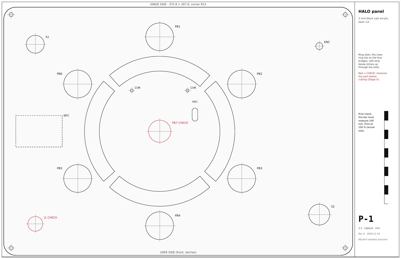
RELAY-6 cut sheets P-1 to P-9 (large PDF, 11 × 17 in, 0.5 MB)
The same panels as DXF cut files (R12, millimetres; layers CUT, ENGRAVE and NOTE; origin at each panel’s lower-left corner), for a laser cutter or a cutting service, with a README and SHA-256 checksums:
RELAY-6 panel DXF cut files (zip, 0.01 MB)
The DXFs are generated from the same geometry file as the sheets. Nothing has been cut or test-fitted yet, so measure the cases and the CHECK parts first.
The sources for everything on this page (firmware, generators, drawings, build guide and BOM data) are at github.com/tjscientist-labs/RELAY-6, licensed GPL v2 or later.
Sources
- Altus Metrum (Bdale Garbee and Keith Packard), TeleLaunch — https://altusmetrum.org/TeleLaunch/ (page last edited 2020-07-14); and TeleLaunch manual, v1.9.22.2 (13 October 2025) — https://altusmetrum.org/AltOS/doc/telelaunch.html. The TeleLCO controller and TeleFireEight pad boxes: 70 cm two-way link with AES-authenticated packets, local and remote keys, 100 µA continuity check, 12 V sealed lead-acid supply, drag-race selection, extension-cord pad cables.
- Edward Robinson (FastEddy59), “Overkill Model Rocket Launch Controller!”, Instructables, 13 April 2020 — https://www.instructables.com/Overkill-Launch-Controller/. Briefcase case with an acrylic panel, Arduino Mega, NRF24 radio, security codes, 15-second countdown, wired backup igniter circuit, emergency stop.
- Edward Robinson (@edwardrobinson6710), “Overkill Model Rocket Launch Controller – Project Summit 2020”, YouTube, 14 April 2020 — https://www.youtube.com/watch?v=ijcLjZP0PUw. Video walkthrough of the same controller.
- National Association of Rocketry, Model Rocket Safety Code — https://nar.org/ModelRocketSafetyCode; and the NAR and Tripoli high-power rocket safety codes (summarized, not quoted).
- Supplier product pages and data sheets for every part in the bill of materials (Heltec, BuyDisplay, SparkFun, Adafruit, Pololu, Digi-Key, Powerwerx, Harbor Freight, Amazon and others), read for prices, hole sizes and ratings on 18 November 2026; each is listed with its part number in the printable BOM.
1.14 Printable Bill of Materials
The full priced bill of materials, with a row for every part, its part number, alternates, supplier, tag and price, three tick boxes (ordered, in hand, fitted), and an order log: