Motors · Volume 2
High-Power Reloadable and Buildable Motors
Composite propellant and grain design, Kn and chamber pressure, reloadable systems and their hardware, assembling a reload, adjustable delays and electronic ejection, the H-to-O classes and the certification ladder, thirty years of federal regulation, and research motors
Introduction
I have flown high-power rockets for many years, as a member of both the National Association of Rocketry and the Tripoli Rocketry Association. One of my favorite rockets, the Estes Mars Snooper, I have built both from the Estes kit and as a much larger high-power rocket. High power changes the motor more than anything else. Above the G class, motors come as reloads: kits of propellant grains and seals assembled by the flyer into a reusable aluminum case. Buying them takes a certification. And at the far end of the hobby, Tripoli members fly research motors whose propellant they have mixed and cast themselves.
The first volume covered black-powder and single-use composite motors up to G. This one starts where that leaves off. It explains how composite propellant burns and how grain shape and the nozzle set the chamber pressure and the thrust curve. It describes the reloadable systems and their hardware and walks through the assembly of a reload. It covers delays and electronic ejection, the high-power classes and the certification levels, the regulation the hobby fought through between 1971 and 2010, and what research motors are.
None of it is a recipe. Propellant formulation and mixing are deliberately left out: the research motors section describes what that work involves and how it is governed, not how to do it.
2.1 What makes a motor high power
High power begins where the model-rocket rules end. In the U.S. fire-code definition, a high-power rocket is one that weighs more than 1,500 g, or carries more than 125 g of propellant, or uses motors totalling 160.01 N·s or more, or uses a motor with an average thrust of 80 N or more. In practice, that means H motors and above, plus a few smaller motors that cross the propellant-mass or thrust lines.
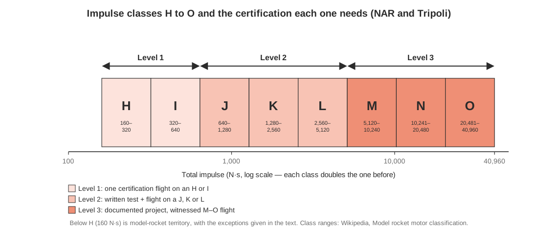
The impulse classes keep doubling:
Table 1 — The impulse classes keep doubling
| Class | Total impulse (N·s) | Certification needed (NAR and Tripoli) |
|---|---|---|
| H | 160.01–320 | Level 1 |
| I | 320.01–640 | Level 1 |
| J | 640.01–1,280 | Level 2 |
| K | 1,280.01–2,560 | Level 2 |
| L | 2,560.01–5,120 | Level 2 |
| M | 5,120.01–10,240 | Level 3 |
| N | 10,240.01–20,480 | Level 3 |
| O | 20,480.01–40,960 | Level 3 |
At the top of their classes, an O motor delivers 128 times the impulse of an H, and 4,096 times that of a C. The U.S. Federal Aviation Administration classes rockets with up to 40,960 N·s of total impulse, the top of O, as Class 2 high-power rockets. Anything bigger is Class 3, which needs individual FAA approval. High-power launches fly under FAA authorizations held by the club or the launch organizer, with a ceiling altitude set for each event.
2.2 Composite propellant, in more depth
Volume 1 introduced ammonium perchlorate composite propellant (APCP): crystalline ammonium perchlorate oxidizer held in a rubbery binder that is also fuel, often with powdered metal. High power uses the same propellant, in much larger grains, so its details matter more.
2.2.1 What it is made of
- Oxidizer. Ammonium perchlorate (AP) is most of the mass. Propellant makers use it in several particle sizes. Ken Kosanke explains that compounding high-performance propellants commonly uses three AP particle sizes, so that the medium particles fill the gaps between the large ones and the fine particles fill the rest. That raises the packing fraction to about 90 % (Peak of Flight #341). More oxidizer in the same volume means more energy per motor.
- Binder. Usually hydroxyl-terminated polybutadiene (HTPB), sometimes PBAN or CTPB. It is mixed as a liquid with the solids and a curing agent, poured or packed into a mold or liner, and cured into a rubbery solid. The binder holds the grain together, makes it tough enough not to crack, and burns as fuel.
- Metal fuel. Aluminum powder raises energy and stabilizes combustion. High-performance mixtures run about 70/15/15 AP/binder/aluminum by mass.
- Additives. Burn-rate catalysts (iron oxides, copper chromite and others), coolants that slow the burn, and the chemicals that color the flame or smoke. In “sparky” propellants, coarse metal particles such as titanium leave the nozzle still burning.
The hobby’s named propellants (White Lightning, Blue Thunder, Mojave Green, Cesaroni’s Blue Streak and the rest, listed in volume 1) are different recipes of these ingredients. They differ in color, smoke, energy and, above all, burn rate.
2.2.2 How fast it burns
Composite propellant burns from its surface inward, layer by layer, at a burn rate measured in millimeters per second. Most formulations burn at 1–3 mm/s at atmospheric pressure and at 6–12 mm/s at about 68 atmospheres. The rate follows an empirical power law, usually called Saint-Robert’s law (or Vieille’s law):
r = a × Pn
where r is the burn rate, P the chamber pressure, and a and n are constants measured for each propellant. The pressure exponent n is the key number. For APCP it is typically 0.3 to 0.5. A low exponent means the burn rate changes only modestly when the pressure changes, and that is what makes APCP a forgiving propellant. It does not detonate, but a motor whose pressure exceeds the strength of its case will burst.
2.3 Kn: how the nozzle and the grain set the pressure
A solid motor runs at the chamber pressure at which the gas it makes and the gas it lets out are in balance:
- Gas made depends on the burning area of the grain, Ab, the burn rate (which rises with pressure) and the propellant density.
- Gas let out depends on the area of the nozzle throat, At, and the chamber pressure: the higher the pressure, the more gas the throat passes.
The ratio of the two areas is the designer’s main control. It is called Kn:
Kn = Ab ÷ At
(Richard Nakka, Solid Rocket Motor Theory — Chamber Pressure). Setting gas made equal to gas out and solving for pressure gives the standard steady-state result:
P = (Kn × a × ρp × c*)1/(1 − n)
where ρp is the propellant density and c* the propellant’s characteristic exhaust velocity, a measure of its combustion energy. The equation says two things that explain most of motor design.
First, pressure follows Kn, and thrust follows pressure. If the burning area grows as the grain burns, Kn grows, the pressure rises and the thrust rises. If it shrinks, the thrust falls. So the shape of the thrust curve is set mainly by how the grain’s burning area changes as it burns: the grain geometry.
Second, the pressure exponent n sets how touchy the motor is. The exponent of Kn in the equation is 1/(1 − n). For n = 0.3, it is about 1.4: a 10 % rise in burning area raises the pressure by about 15 %. For n = 0.7 it would be about 3.3, and the same 10 % rise in area would raise the pressure by about 37 %. As n approaches 1, the motor has no stable operating point at all. This is why a crack in a grain, a gap between grain and liner, or a piece of debris lodged in the throat is so dangerous: each one changes Kn suddenly, and the pressure follows. It is also why the makers’ instructions forbid swapping parts between reload kits. A nozzle with a different throat from the one a grain was designed for changes Kn for the whole burn.
Kn also has a lower limit. If the pressure is too low, combustion becomes unstable and the motor chuffs: it burns in puffs, with long pauses, instead of steadily. Motor design is therefore a matter of keeping Kn, and with it the pressure, inside a window for the whole burn: high enough for stable burning and good efficiency, low enough for the case.
2.4 Grain geometry
Most of a motor designer’s control over the thrust curve comes from the shape of the grain. Ken Kosanke’s survey of the geometries used in model and high-power motors (Peak of Flight #341) is the basis for this section and for Figure 2.
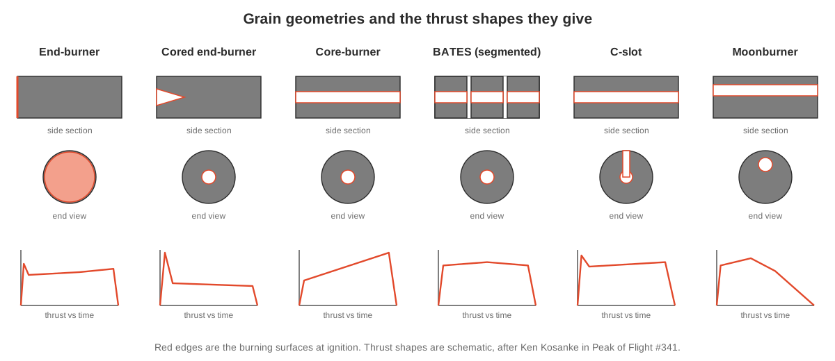
- End-burner. A solid rod inhibited on its sides, burning from one end like a cigarette. The burning area barely changes, so the thrust is nearly neutral (constant) and long. It is low in thrust and it heats the case for a long time. Contest motors and long-burning composites use it.
- Cored end-burner. An end-burner with a short core or cone at the nozzle end, as in most black-powder motors (volume 1). The core gives an initial spike that gets the rocket off the rod.
- Core-burner. A thick tube burning from the core outward, with the case or liner protecting the outside. It was the first geometry used in amateur composite motors. As the core widens, its surface grows, so a long single core-burner is strongly progressive: the thrust rises through the burn and the pressure peaks at the end.
- BATES. The core-burner cut into short segments, each burning on its core and both ends. Named for the U.S. Air Force’s Ballistic Test and Evaluation System, it is widely used in hobby reloads (though not universally: the G64 reload in Figure 4 uses C-slot grains). As each segment burns, its core grows (more area) while it gets shorter from both ends (less area), and the two effects can be made almost to cancel.
- C-slot. A single grain with a lengthwise slot cut into it, usually as deep as the grain radius. It approximates neutral burning in a single long grain without the large pressure rise of a plain core-burner. Its short ignition spike comes from erosive burning in the slot.
- Moonburner. A single grain with its core off-center, tangent or nearly tangent to the outside of the grain. It has a thick web, a long burn and a long tail-off. AeroTech’s first product in 1982 was a G30 “moonburning” motor.
- Finocyl (“fins on cylinder”). A core with four to eight slots radiating from it. The large initial area gives high thrust for a short burn. It stands in for the star-shaped cores of professional motors, because a slotted mandrel is easier to make than a star.
Two side effects limit every geometry. Erosive burning is the extra burn rate caused by hot gas rushing along a propellant surface, which is worst at the aft end of a long, narrow core: it causes ignition spikes and can raise the pressure dangerously. Designers keep the core large enough, relative to the throat, to limit it. Case heating matters for geometries that expose the liner early, such as the C-slot and the moonburner.
2.4.1 BATES grains and Kn
The BATES grain is worth a closer look, because so many reloads are built from it. For each segment, three things change as it burns: the core diameter grows, the outer diameter stays fixed against the liner, and the segment gets shorter from both ends. Whether the burning area rises, falls or stays level depends on the segment’s length.
Kosanke gives the rule of thumb for an approximately neutral burn:
L = (3 · OD + ID) ÷ 2
where L is the segment length, OD its outside diameter and ID its core diameter. That length makes the burning area at burnout equal to the area at ignition. Shorter segments give a regressive curve, with thrust falling through the burn. Longer segments give a progressive one (Figure 3).
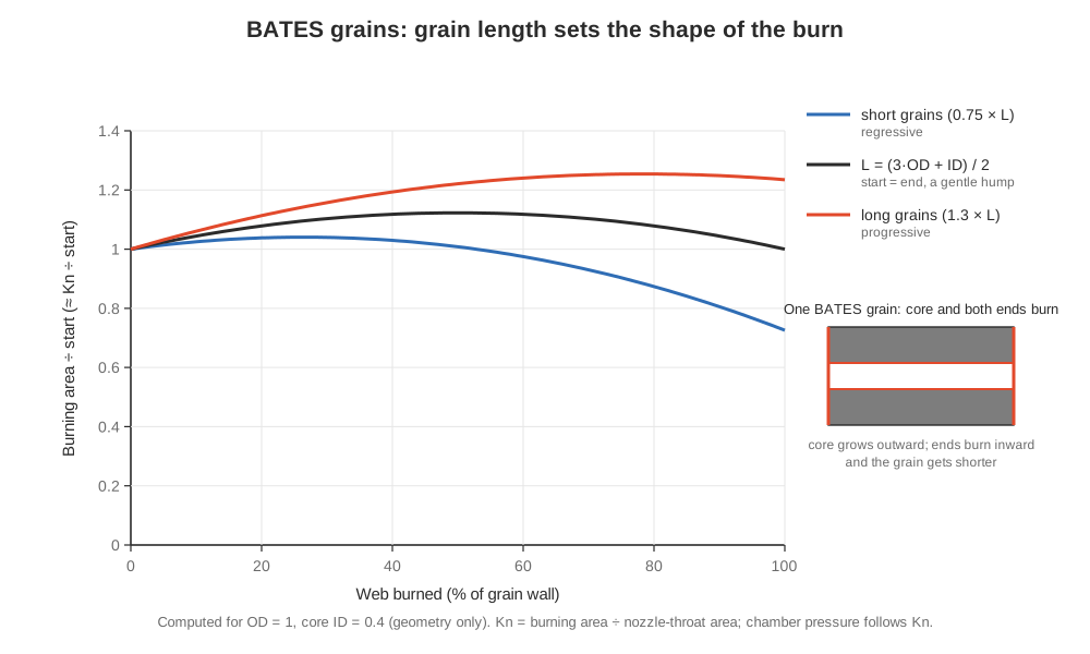
Even the “neutral” length is not perfectly flat: in the middle of the burn its area is about 12 % above the start in Figure 3. Real motors are tuned further by the number of segments, the core size, the nozzle throat, and sometimes by inhibiting the outer ends of the end segments. The certified thrust curve, not the geometry, is what a flyer simulates with.
2.5 Reloadable motors
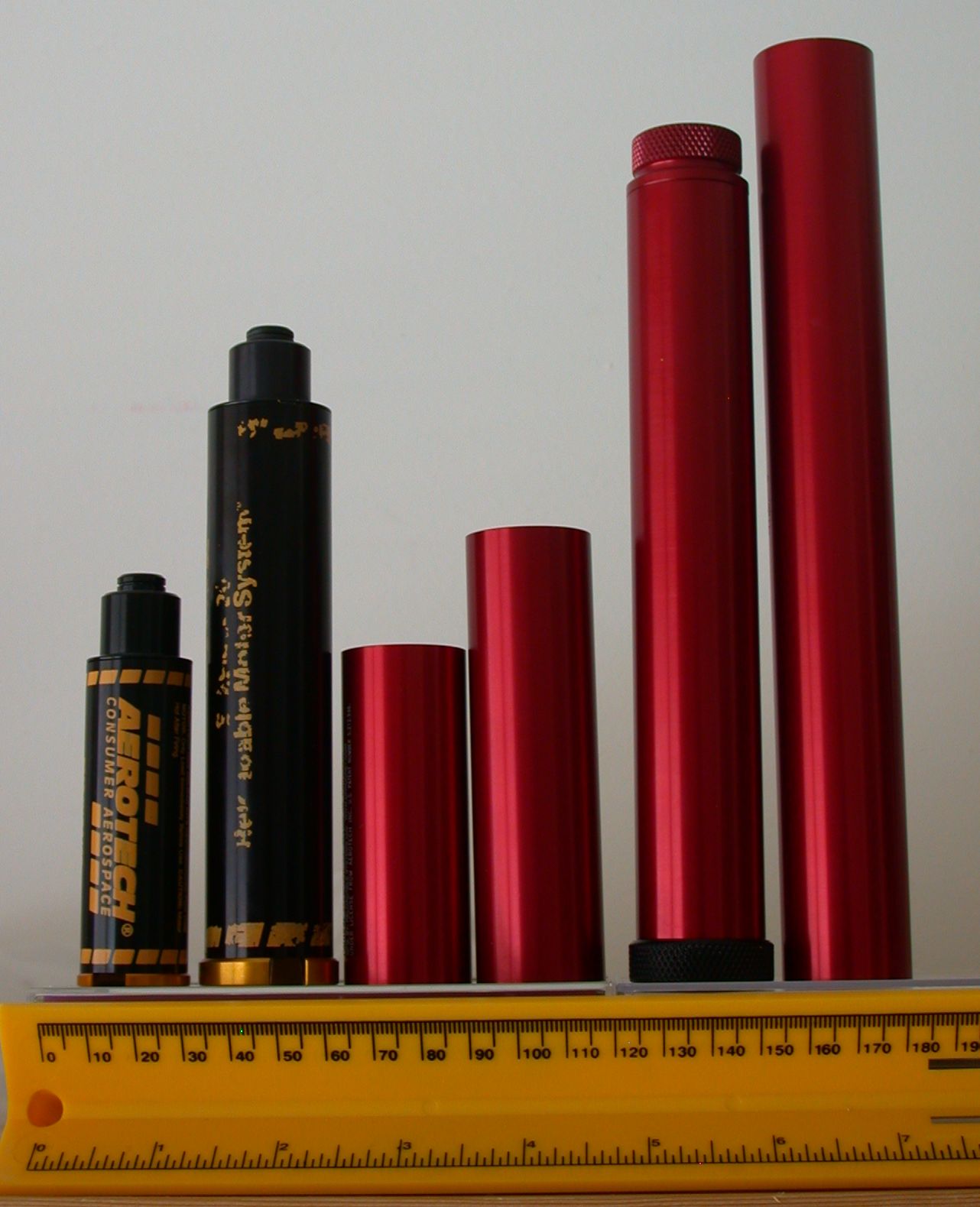
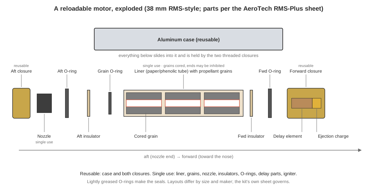
A reloadable motor separates the parts that survive a firing from the parts that do not. The case (an aluminum tube) and the closures that seal its ends are kept and cleaned. The reload kit contains everything consumed: the propellant grains in a paper or phenolic liner, a nozzle, O-rings and insulating washers, the delay and ejection parts, and an igniter. A reload costs much less than a single-use motor of the same class, because the expensive machined hardware is bought once (Peak of Flight #209).
2.5.1 The systems
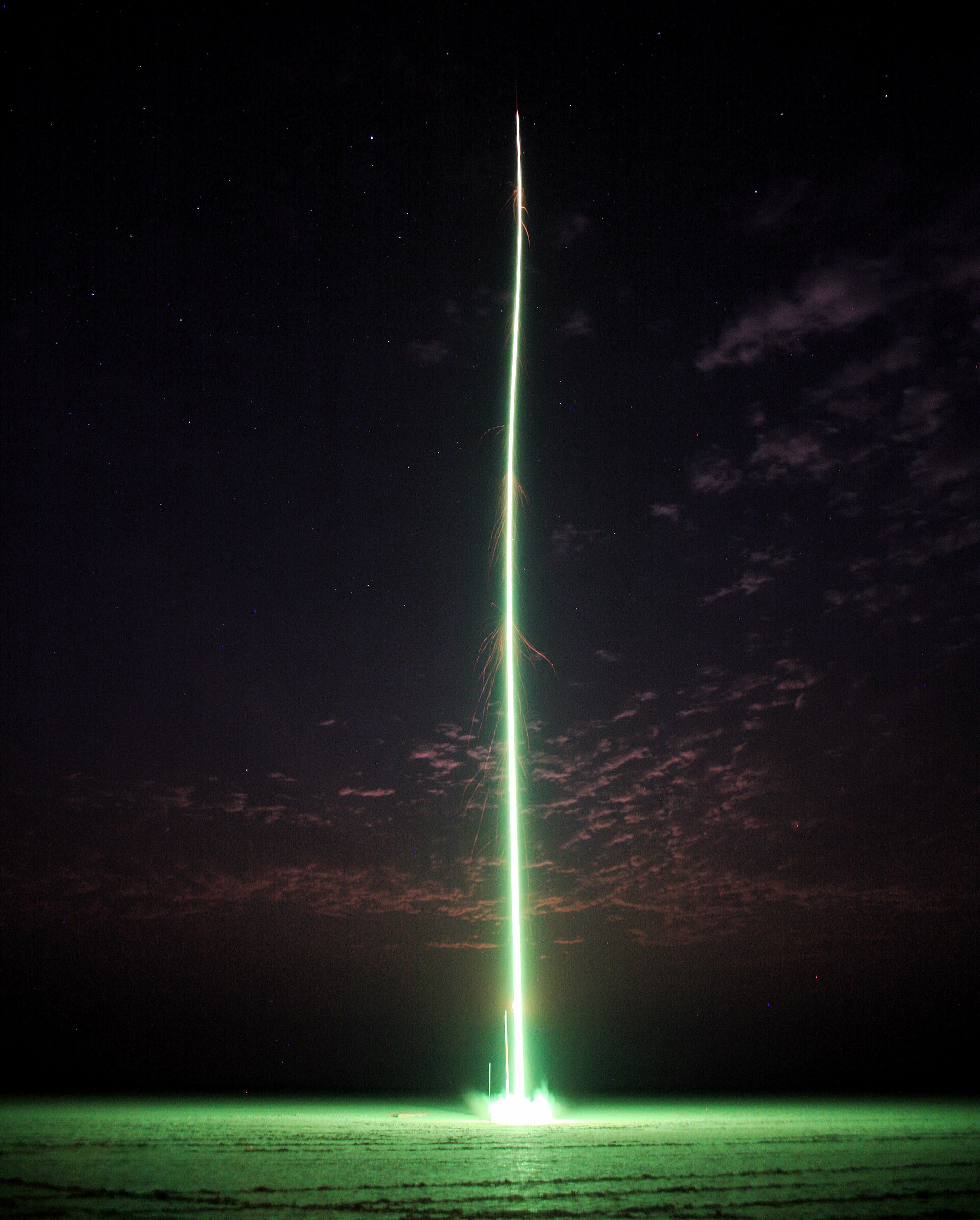
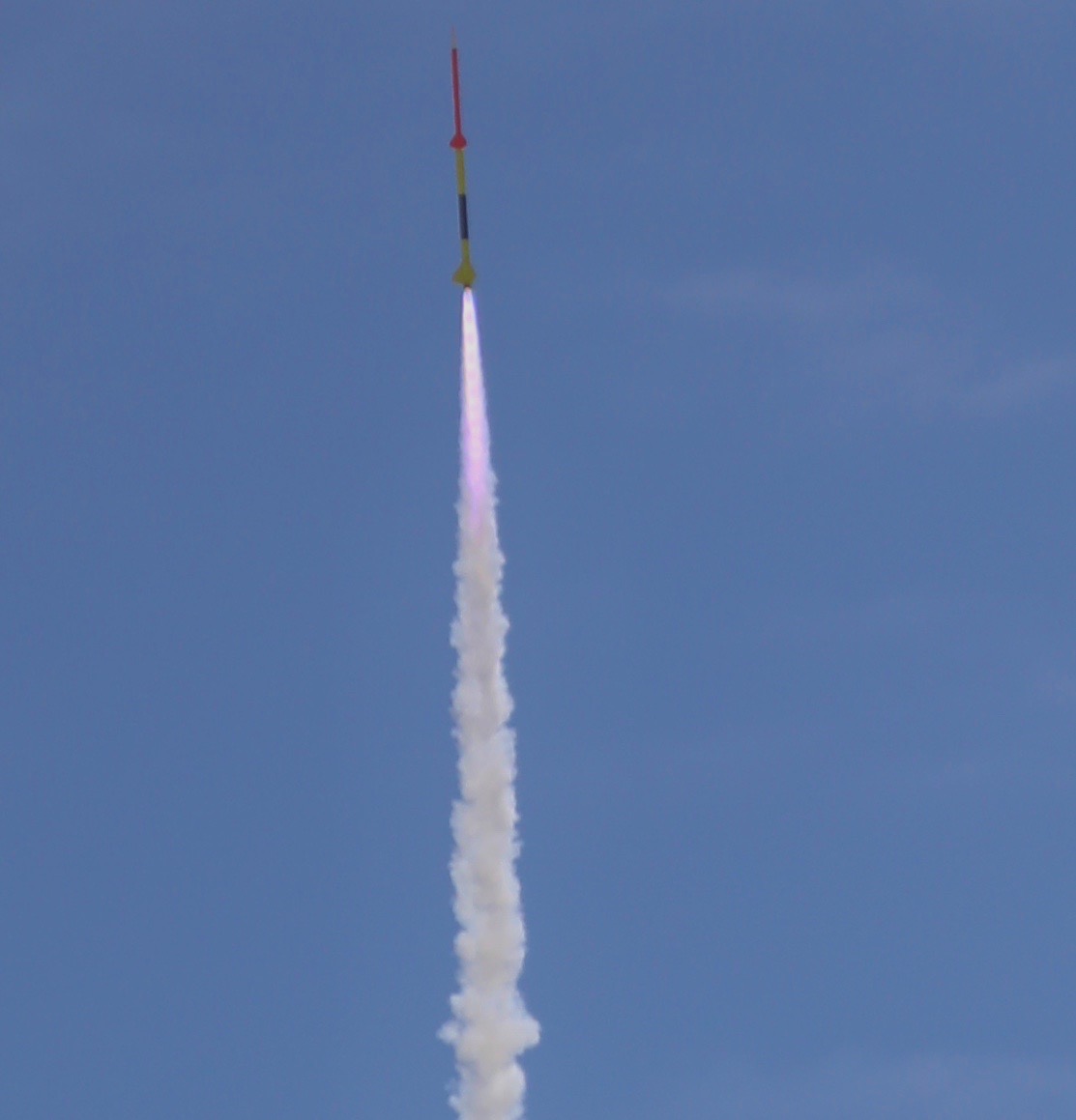
AeroTech RMS. AeroTech’s Reloadable Motor System was introduced to the high-power market in 1990 under the name of its then owner, Industrial Solid Propulsion, and extended to model-rocket sizes in 1991. The RMS-Plus system, with a redesigned delay and seal, was announced in 2000. AeroTech’s hardware is named by diameter and the range of reloads it takes, in N·s: an RMS-29/40-120 case takes 29 mm reloads of roughly 40 to 120 N·s, and the 723 N·s J500G that lights the opening photograph is an RMS-38/720 reload. Reloads are sold for a specific hardware size and are not interchangeable between sizes. AeroTech also sells DMS single-use high-power motors (38 and 54 mm DMS motors were added in 2014) and large single-use motors up to O.
Cesaroni Pro-series. Cesaroni Technology, of Ontario, makes the Pro29, Pro38 and Pro54 systems, among others, sold under the Pro-X name. A Cesaroni reload comes pre-assembled: the grains, liner, nozzle and seals form one module that threads into the case, with the delay and ejection charge in a separate module at the front. Cesaroni’s instructions describe reloading as a three-step job: set the delay, slide the delay module into the liner, and thread the assembly into the case. After the flight, the spent module is unscrewed and thrown away, and “there are no reusable parts” in it. Cesaroni adds the total impulse to the front of the motor code: an 800J360-15A is an 800 N·s J motor with 360 N average thrust and a 15-second adjustable delay.
Others. The commercial high-power makers have also included Loki Research and Gorilla Rocket Motors, and Kosdon, whose motors AeroTech licensed in 2000 and released as “Kosdon by AeroTech” in 2001. Hybrid motors, which burn a solid fuel grain with a liquid oxidizer (usually nitrous oxide) loaded at the pad, are a separate branch of high power: AeroTech’s RMS/Hybrid line dates from 1995.
2.5.2 Case hardware
The hardware is simple, precise and unforgiving of damage:
- The case is a thin-walled aluminum tube, usually anodized, threaded inside at one or both ends. It takes the full chamber pressure, so dents and scratches matter. Both AeroTech and Cesaroni say a damaged case must not be used.
- The aft closure holds the nozzle and takes the thrust. On AeroTech hardware it is a separate threaded part; on Cesaroni hardware a thrust ring is part of the disposable reload module.
- The forward closure seals the front of the case. It carries the delay and ejection charge, or, as a plugged closure, nothing at all, for use with electronic deployment.
- The seals are O-rings, renewed with every reload. Insulating washers and the liner keep the hot gas off the aluminum. Large AeroTech reloads use an additional forward seal disk to seal the front of the liner.
High-power motor mounts hold the case with a screw-on retainer or another positive mechanical device. AeroTech’s instructions call for “positive mechanical means” so the motor cannot be pushed out at ejection.
2.6 Assembling a reload, step by step
What follows is a summary in reference voice of two makers’ instructions, so that the sequence makes sense. It is not a substitute for the sheet in the kit, which is written for that reload and takes precedence over anything here. AeroTech’s own instructions say in capitals that the sequence of assembly is extremely important.
2.6.1 An AeroTech RMS reload (38 mm, single grain)
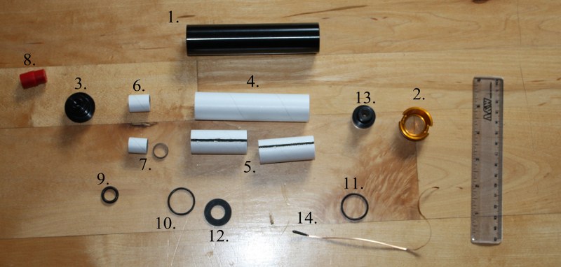
From AeroTech’s RMS-Plus instructions for a 38/120 reload (Figure 6):
Before starting. Do not open the kit until ready to use it. Study the drawings and parts list; contact the maker if anything is missing or damaged. Work on a clean surface away from flames and other motors. Have grease (AeroTech specifies Super Lube or similar), a hobby knife and damp wipes ready. Grease all threads and every O-ring except the grain O-ring, so that the seals seat and the threads do not seize.
1. Forward closure. Assemble the smoke-charge (delay) element, its insulator tube and its O-ring, as drawn. Fit the neoprene spacer into the closure’s cavity, grease the cavity, and push the delay assembly in after it, O-ring end first. With a plugged closure, fill the spacer’s opening with grease instead.
2. Grain and liner. Grease one end of the propellant grain and slide it into the liner. Push the liner into the case until it is recessed equally at both ends.
3. Forward end. Place the forward insulator washer against the greased end of the grain, seat the greased forward O-ring behind it, fill the insulator’s center with grease, and thread the forward closure in by hand until it seats.
4. Aft end. Seat the grain O-ring against the aft face of the grain, then the aft insulator against the liner, then the greased aft O-ring. In this end-burning kit the supplied Copperhead igniter goes in next, its coated end slipped into the gap between the aft insulator and the grain. Thread the nozzle over the igniter lead and push it into the aft O-ring. Thread the aft closure in by hand until it seats.
5. Igniter and flight preparation. Bend the igniter lead into an S, vent the plastic nozzle cap by cutting off a corner, and push it on to hold the igniter. Install the motor in the rocket with positive retention, prepare the recovery system and fly under the Tripoli safety code and NFPA 1127.
6. Cleaning. As soon as possible after the flight, and within a day (residue becomes hard to remove and corrodes the aluminum), remove both closures, discard the liner, nozzle, O-rings, insulators and delay parts, and wipe all residue from the case and closures. AeroTech warns that smoke-charge residue left in the forward closure can cause a gas leak on the next flight. Grease the threads and the inside of the case lightly, reassemble the metal parts and store them dry.
2.6.2 A Cesaroni Pro38 reload
Cesaroni’s Pro38 instructions reduce the job to three steps:
- Set the delay (see the next section) with Cesaroni’s delay tool, or move the ejection powder to an electronic system.
- Fit the delay module into the front of the reload’s plastic liner with a gentle twist. A small gap at the shoulder is normal.
- Thread the reload into the case from the rear and tighten it firmly by hand. The sheet allows a small gap between the reload’s thrust ring and the end of the case. A gap of more than 1/16 in (1.6 mm) means something is wrong and the motor should be taken apart and reassembled.
After the flight, the reload is unscrewed and thrown away. Any delay module left in the case is pushed out from the front with a wooden or plastic tool: metal tools can scratch or dent the case. Residue, if any, is washed out with hot soapy water.
2.6.3 Igniters at the pad
The high-power rule, quoted on Cesaroni’s sheet from NFPA 1127, is that the igniter is installed at the launcher or in the area the safety monitor designates, with the rocket pointed in a safe direction. Igniter leads stay shunted (twisted together or capped) until the rocket is on the pad and the launch system is safe, motors are never stored with igniters in them, and an aborted launch means the igniter comes out and the shunt goes back on.
2.7 Delays and ejection
2.7.1 Adjustable delays
High-power rockets differ more from one another than model rockets do, so the “right” delay varies more. Both main makers sell delays that the flyer can shorten:
- Cesaroni fits every Pro-series reload with a full-length delay. Its delay tool, a drill guide with notched settings, shortens it by 3, 5, 7 or 9 seconds, down to a minimum for each motor. A Pro38 marked -15A, for example, can be set to 15, 12, 10, 8 or 6 seconds. The adjustment cannot be undone. Cesaroni recommends doing it outdoors, in the field, during rocket preparation, and soaking the drilled-out delay residue in water for at least an hour before throwing it away, which dissolves its oxidizer.
- AeroTech reloads are sold with standard delays, and separate delay kits change them. Its adjustable-delay motors (marked “A”, as in I284W-14A) and its DMS single-use motors are shortened with AeroTech’s delay-drilling tool.
Delay selection works as in volume 1: simulate the flight, read the optimum delay, and set the nearest one. For high-power flights the delay is often a backup rather than the primary deployment (below).
2.7.2 The ejection charge
A Pro38 reload’s ejection charge is 1.3 g of FFFFg black powder. If a rocket needs more, Cesaroni’s advice is not to remove the charge’s white cap but to add powder on top of it and seal the cavity with tape. Some reloads, such as AeroTech’s Warp-9 kits, come with no ejection charge at all and must be flown with a timer, an altimeter or a radio-commanded recovery system.
2.7.3 Motor ejection versus electronics
Most high-power rockets fly with an altimeter that fires the ejection charges itself: at apogee for a drogue or the main parachute, and often at a low altitude for the main parachute in dual deployment. With electronics doing the work, the motor’s delay becomes the backup, or is removed altogether:
- Cesaroni’s instructions describe taking the black powder out of the delay module and transferring it to the electronics’ charge holder.
- A plugged forward closure seals the front of the motor completely, for rockets that rely on electronics alone.
Level 3 certification (below) requires redundant electronic deployment. How altimeters, charges, dual deployment and GPS tracking work belongs to the Payload Electronics and Recovery dives.
2.8 When a reload fails
Reloads fail in their own ways. Each one is a version of the Kn problem above: hot gas finding a path it was not designed for.
- Seal failures. A missing, damaged or wrongly seated O-ring lets gas past the closure. The jet cuts through the aluminum and the motor mount. Leftover residue in a forward closure can do the same, which is why AeroTech insists on a clean closure.
- Liner and grain defects. David Anisman traced a CATO in his Zephyr to a defect in the motor liner just forward of the aft closure. The flaw let the thrust vent sideways. It burned through the case and the motor mount tube, and the sideways thrust, at perhaps 60° to the vertical, cartwheeled the rocket (Peak of Flight #606).
- Wrong parts. A nozzle, spacer or grain from another kit changes Kn. AeroTech’s instructions say not to interchange parts and not to reuse the liner, nozzle or O-rings.
- Damaged hardware. A dented or scratched case can split.
A CATO is not always the flyer’s fault: Anisman wrote that his three CATOs were all motor problems. But a careful assembly, done exactly to the sheet, rules out the failures that are.
2.9 Certification: the levels and what they allow
High-power motors are sold only to flyers certified by the NAR or Tripoli, and only up to their level. The two organizations’ programs differ in detail, but they have the same three levels and accept each other’s certifications.
2.9.1 Level 1: H and I
The candidate builds a rocket for an H or I motor and flies it before a qualified witness. The NAR requires the candidate to be at least 18 at the time of certification. The motor preparation, flight and recovery are witnessed, and the rocket must come back in a state to fly again. A successful flight lets the flyer buy and fly H and I motors.
2.9.2 Level 2: J, K and L
A Level 1 flyer passes a written test on high-power rocketry and then makes a successful flight on a J, K or L motor. Level 2 opens J, K and L motors.
2.9.3 Level 3: M, N and O
Level 3 is a project. The candidate works with the organization’s reviewers (the NAR’s Level 3 Certification Committee, the L3CC; the Tripoli Advisory Panel, the TAP), documents the design and construction of the rocket, and flies it on an M, N or O motor. The rocket must have redundant electronic deployment. The NAR requires the construction and recovery documents to reach the reviewing L3CC member at least five days before the flight attempt. The flight is witnessed by two people, one of them an L3CC member. Keith Packard notes that the demands of Level 3 are why Level 2 flyers far outnumber Level 3 flyers.
Each level must be passed in order, and certification flights are made on certified commercial motors. A Tripoli certification stays current while the member’s dues are paid.
2.10 Regulation: how the hobby got here
High-power motors have been regulated by three federal agencies, each for its own reason. The longest fight was with the Bureau of Alcohol, Tobacco, Firearms and Explosives (ATF), and its outcome still shapes how motors are bought and stored.
2.10.1 ATF and the APCP case
ATF regulates explosives under federal law, and it had put ammonium perchlorate composite propellant on its list of explosive materials since the first list was published in 1971. Small motors were exempt. The 62.5-gram limit that still marks the boundary of model-rocket motors traces back to a 1981 ATF exemption that borrowed the Department of Transportation’s standard for small toy propellant devices. ATF’s later rule-writing dropped the toy-motor language by mistake in the late 1990s, but the agency went on applying the exemption.
Larger motors were a different matter. Through the 2000s, under the Safe Explosives Act of 2002 and the enforcement that followed, anyone acquiring motors with more than 62.5 g of propellant, or reload kits that would make such motors, needed a federal Low Explosives User Permit (LEUP). That meant a background check and storage that met the explosives regulations, typically an approved magazine. Clubs that held a permit could sponsor launches and supply motors to their members. Tim Van Milligan, writing in 2004, blamed the post-2001 regulation and enforcement for discouraging a generation of propulsion-minded flyers (Peak of Flight #135). By 2008 he was writing that he looked forward to the end of the NAR/Tripoli lawsuit against ATF so that the regulations could be relaxed: they were already affecting what Apogee could sell (Peak of Flight #209).
The lawsuit, Tripoli Rocketry Association v. ATF, was brought by Tripoli and the NAR and argued that APCP is not an explosive at all: it burns, but it does not explode. Its course:
Table 2 — The lawsuit, Tripoli Rocketry Association v. ATF, was brought by Tripoli and the NAR and argued that APCP is not an explosive at all: it burns, but it does not explode. Its course
| Date | Event |
|---|---|
| 2004 | The district court rules for ATF, deferring to the agency’s technical judgment. |
| 10 February 2006 | The U.S. Court of Appeals for the D.C. Circuit holds that ATF’s classification of APCP cannot be sustained on the record and sends the case back to the agency. |
| 11 August 2006 | ATF publishes its final rule on hobby rocket motors, effective 10 October 2006. It writes the 62.5 g exemption back into the regulations (motors and reload kits of up to 62.5 g of propellant) while still treating APCP as an explosive. |
| 16 March 2009 | The U.S. District Court for the District of Columbia vacates ATF’s classification of APCP as an explosive. |
| 8 January 2010 | ATF publishes its new list of explosive materials, with APCP removed and the note that APCP “is no longer regulated under the Federal explosives laws”. |
Since then ATF has not regulated APCP motors as explosives, so the LEUP and magazine requirements for APCP no longer apply to them. Black powder is still on ATF’s list, which matters for the black-powder ejection charges and delays inside motors and for loose ejection powder. The current rules for those are a question for ATF’s regulations and for state and local law, not this volume.
2.10.2 CPSC: the age limit
The Consumer Product Safety Commission’s exemption for model-rocket motors covers only small, preloaded, non-metallic motors under 80 N·s (volume 1). Motors outside it, which includes every reload kit and every high-power motor, are sold to adults only. Reload instruction sheets carry the warning that sale to persons under 18 is prohibited by federal law. Cesaroni prints “for use only by certified high-power rocketry users 18 years of age or older” at the top of its Pro38 sheet.
2.10.3 DOT: shipping
The Department of Transportation regulates rocket motors as hazardous materials in transport. Small motors travel under special arrangements: as AeroTech has described it, most U.S. manufacturers ship motors of up to 62.5 g of propellant under a DOT special permit (SP 7887) that reclassifies them as flammable solids. Larger motors and reloads go by ground with hazardous-materials packaging and fees. In 2008 Tim Van Milligan wrote that UPS and FedEx charged a hazmat fee of $20 per box, which is why AeroTech designed its loadable G motors to come in parts under 30 g each, so they could be shipped by mail (Peak of Flight #209). Carrier rules and fees change, and the dealer is the current authority. Many flyers avoid the issue by buying from the vendors at large launches.
2.10.4 FAA: the airspace
Rockets heavier or more powerful than Class 1 model rockets fly only under FAA authority. High-power launches (Class 2) are flown under waivers or authorizations obtained by the club or launch organizer, which set the altitude ceiling and the times for each event.
2.11 Research motors and making propellant
A research motor, which Tripoli calls experimental (EX), is a motor that has not been commercially certified, usually because its flyer made it. Research flying is the hobby’s propulsion laboratory: it is where flyers develop new grain designs, propellants and motors far larger than any sold, such as the P10000 in Figure 8.
2.11.1 Who may fly them, and where
- Tripoli supports research motors. It allows experimental motors for members certified at Level 2 or above, and its safety code permits research motors at Tripoli launches. Research motors that were sold for profit are excluded: a research motor is the flyer’s own work, not an uncertified commercial product. Research motors cannot be used for certification flights. A unified Tripoli safety code that took effect on 1 May 2022 did away with the old separate “research launches” and “commercial launches”; there are now simply Tripoli launches, at which research motors may fly.
- The NAR does not take part. Its high-power safety code requires certified, commercially made motors, used only as the manufacturer recommends.
The details, including the impulse a flyer may use at each level and any extra requirements for very large motors, are in Tripoli’s current safety code and are the authority for anyone considering research work.
2.11.2 What making a motor involves
Making a research motor is a manufacturing job. It means designing a grain and nozzle to keep Kn and the pressure inside the case’s limits; formulating, mixing and casting propellant; curing and machining the grains; and static-testing motors on an instrumented thrust stand before any of them flies. Tim Van Milligan’s 2004 list of what a first motor needs, drawn from a review of a book on home-made motors, gives a sense of the scale: a mill, a scale, a vacuum pump and chamber, a lathe, a thrust stand and its software, and custom-made molds, mandrels and tools, before any chemicals are bought. His estimate was that the first successful motor would cost hundreds of dollars, far more than a commercial one (Peak of Flight #135).
2.11.3 The hazards
The hazards are real, and they are why the hobby treats motor-making as a separate and supervised activity:
- Mixing and handling. Oxidizers, metal powders and catalysts are hazardous as raw materials, and an uncured or partly mixed propellant can be ignited by friction, static or heat. Tim Van Milligan pointed out in 2004 that professional motor makers, including Quest, Cox and AeroTech, had had fatal accidents in their own production facilities (Peak of Flight #135).
- The motor itself. An untested design can burst on the stand or the pad, because a small error in the burning area or the throat can raise the pressure many times over (see Kn).
- The law. APCP is no longer an ATF-regulated explosive, but black powder is. Making any propellant is also subject to state and local fire codes, zoning and permit rules, which vary widely. Tim Van Milligan’s 2004 warning that mixing propellant in an apartment could lead to prison came from the ATF era, but the underlying point stands: the legal position must be checked before any work starts, not after.
This volume does not describe propellant formulations, mixing or casting. Those belong in Tripoli’s mentoring and research programs, where experienced research flyers supervise the work.
2.12 Storage, safety and disposal
2.12.1 Storage
Reload kits and single-use high-power motors keep best cool and dry, in their original packaging, away from igniters. Cesaroni prints a use-within date on its Pro38 reloads (one year from manufacture) and a storage temperature range of −5 to 30 °C. Cases are stored clean and lightly greased.
2.12.2 Fire
AeroTech’s instructions state that, in its tests, the pyrotechnic components of RMS reloads did not explode in fires and normally would not ignite without direct flame, and then burned slowly. Its advice for fighting a fire involving them is water, aimed to keep the components below their 550 °F (288 °C) autoignition temperature. Foam and carbon-dioxide extinguishers will not put out burning propellant of this kind.
2.12.3 Disposal
Damaged or defective AeroTech reload kits go back to RCS. Cesaroni’s instructions give a disposal method for unused reloads: remove the grains from the liner, place them with the forward closure in a shallow hole away from anything combustible, install an igniter, and fire it electrically from at least 10 m away. The remains can then go in household trash. A misfired high-power motor is reported to the range safety officer and dealt with under the range’s procedures.
2.12.4 The safety codes
At NAR launches the NAR High Power Rocket Safety Code applies; at Tripoli launches, Tripoli’s code; and behind both, NFPA 1127, Code for High Power Rocketry. All of them require certified motors (Tripoli’s also provides for research motors), positive motor retention, igniters installed only at the pad, minimum distances that grow with the motor’s impulse, and the range safety officer’s approval of every flight.
2.13 Where this volume hands off
- Airframes for high power, motor mounts and retainers, and the certification rockets themselves: the High-Power Rockets dive.
- Altimeters, electronic deployment, staging electronics, GPS and telemetry: the Payload Electronics dive.
- Drogues, mains, dual deployment and ejection-charge sizing: the Recovery dive.
- Pads, rails, igniters and launch controllers: the Launchers dive.
- Simulating high-power flights and choosing motors in RockSim: the RockSim dive.
- Black-powder and single-use composite motors, certification testing, reading thrust curves and choosing a motor: volume 1 of this dive.
Sources
- Ken Kosanke, “Terminology of Model Rocketry — Part 3” (packing fraction and propellant grain geometry), Peak of Flight #341 (2013). (Library copy)
- Tim Van Milligan, “How To Make Your Own Rocket Motors”, Peak of Flight #135 (2004). (Library copy)
- Tim Van Milligan, “What is a Loadable Rocket Motor?”, Peak of Flight #209 (2008). (Library copy)
- David Anisman, “Zephyr Repair After a Motor CATO”, Peak of Flight #606 (2023). (Library copy)
- Tim Van Milligan, “Picking Propellant Types from Aerotech and Cesaroni”, Peak of Flight #624 (2024). (Library copy)
- AeroTech/RCS Rocket Motor Components, High-Power RMS-Plus Assembly and Operation Instructions, RMS-38/120 G69N-P reload, P/N 20069-2, rev. 7 May 2007 — https://d3l66gvjdr7rqw.cloudfront.net/Templates/170652/myimages/38_120n_eb_in_20069-2_1642635010361.pdf.
- Cesaroni Technology, Pro38 High-Power Reloadable Rocket Motor System: Assembly and Operating Instructions (dealer copy) — https://sunwardhobbies.ca/wp-content/uploads/2012/07/Pro38-Hardware-Instructions.pdf.
- AeroTech/Quest, company history — https://aerotech-rocketry.com/pages/history.
- Richard Nakka, Solid Rocket Motor Theory — Chamber Pressure — https://www.nakka-rocketry.net/th_pres.html.
- Bureau of Alcohol, Tobacco, Firearms and Explosives, “Commerce in Explosives — Hobby Rocket Motors”, final rule, Federal Register vol. 71, no. 155 (11 August 2006) — https://www.govinfo.gov/content/pkg/FR-2006-08-11/html/06-6862.htm.
- Bureau of Alcohol, Tobacco, Firearms and Explosives, “Commerce in Explosives; List of Explosive Materials”, Federal Register (8 January 2010) — https://www.govinfo.gov/content/pkg/FR-2010-01-08/html/2010-45.htm.
- Tripoli Rocketry Association v. Bureau of Alcohol, Tobacco, Firearms and Explosives, 437 F.3d 75 (D.C. Cir. 2006) — https://media.cadc.uscourts.gov/opinions/docs/2006/02/04-5453a.pdf.
- U.S. Code of Federal Regulations, 16 CFR 1500.85(a)(8) — https://www.law.cornell.edu/cfr/text/16/1500.85.
- Keith Packard, “Rocket certification” — https://keithp.com/rockets/certification.
- National Association of Rocketry, Level 3 certification presentations (NARCON 2003 and 2017) and High Power Rocket Safety Code (summarized, not quoted).
- thrustcurve.org (John Coker), motor data pages for the AeroTech G64W, G69N, H128W, J500G and O5040 and the Cesaroni J1520; “Motor Certification” — https://www.thrustcurve.org/info/certification.html.
- Wikipedia, Ammonium perchlorate composite propellant (composition, burn rates, pressure exponent), High-power rocketry (the NFPA definition, FAA classes, Tripoli’s support for experimental motors) and Model rocket motor classification (impulse classes, certification levels), for orientation.
- Secondary reports used only for points flagged in the dive card: a Rocketry Forum thread on Tripoli’s unified safety code (effective 1 May 2022) and on AeroTech Product Bulletin 2008-1 (forward seal disks); third-party summaries of Tripoli’s research-motor rules; and published copies of the DOT SP 7887 shipping permit terms.